-
Scam Alert. Members are reminded to NOT send money to buy anything. Don't buy things remote and have it shipped - go get it yourself, pay in person, and take your equipment with you. Scammers have burned people on this forum. Urgency, secrecy, excuses, selling for friend, newish members, FUD, are RED FLAGS. A video conference call is not adequate assurance. Face to face interactions are required. Please report suspicions to the forum admins. Stay Safe - anyone can get scammed.
-
Several Regions have held meetups already, but others are being planned or are evaluating the interest. The Calgary Area Meetup is set for Saturday July 12th at 10am. The signup thread is here! Arbutus has also explored interest in a Fraser Valley meetup but it seems members either missed his thread or had other plans. Let him know if you are interested in a meetup later in the year by posting here! Slowpoke is trying to pull together an Ottawa area meetup later this summer. No date has been selected yet, so let him know if you are interested here! We are not aware of any other meetups being planned this year. If you are interested in doing something in your area, let everyone know and make it happen! Meetups are a great way to make new machining friends and get hands on help in your area. Don’t be shy, sign up and come, or plan your own meetup!
You are using an out of date browser. It may not display this or other websites correctly.
You should upgrade or use an alternative browser.
You should upgrade or use an alternative browser.
New 10" X 54" mill ordered.
- Thread starter John Conroy
- Start date
That would have been smart but no I just winged it and it turned out OK.
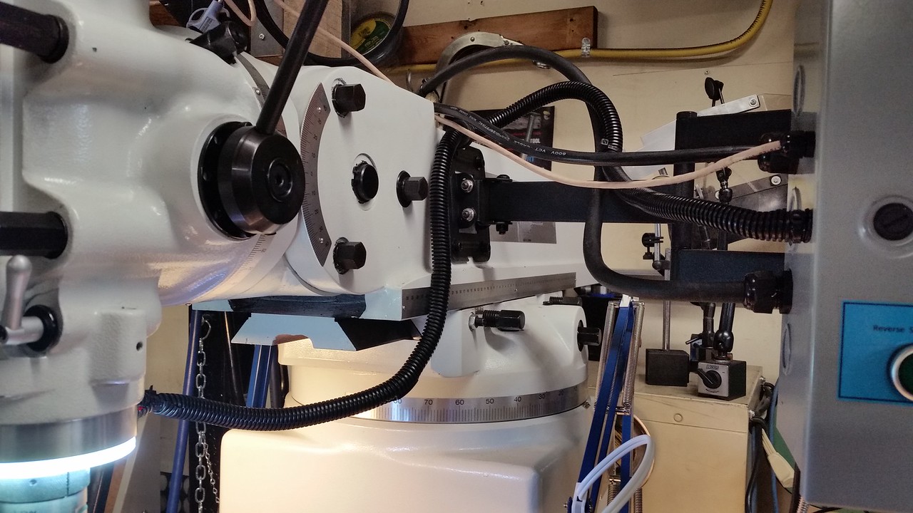
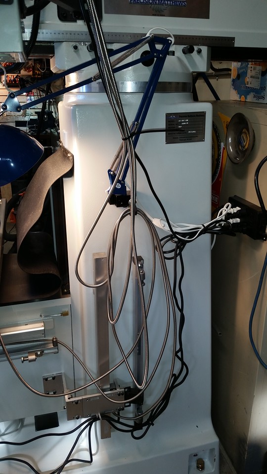
I installed the quill DRO that was on my old mill. I made a new plug to fit the quill stop. It has M5 female threads so it can be attached to the sliding part of the scale. It drilled and tapped a through hole in it at a 45 degree angle for a M5 set screw to retain it in the quill stop. I had to drill 1 new mounting hole in my bracket as the original screw hole did not line up with the hole in the new mill.


It is showing millimeters in the pictures. It has .001" resolution. It's a normal Norman Igaging scale.
Someone was asking on another Bridgeport/clone post about mounting a shorter typical X,Y DRO scale on the quill & plug it into a 4th port on DRO box. John's picture shows why that's a PITA if even possible. Even with smaller scale systems there just isn't much real estate to mount brackets & scale & encoder cover without interfering with other mechanical things. The dedicated vernier style quill kits are the way to go. Nice clean installation, access to stop nut, no cables to mess with. There is one thing I learned on mine & that is to run a DTI up & down the scale to ensure its aligned to quill movement so there is no scale misalgnment or tension in the reader head. Sometimes the casting surfaces aren't as reliable as one would assume so might needs bit of shimming here & there. On that front, one trick I saw was to drill set screw holes in mounting brackets so you can micro adjust them in & out to correct plane geometry relative to casting surfaces & that does away with washers & shim stock. Its kind of situation specific but its a good idea IMO.
It is showing millimeters in the pictures. It has .001" resolution. It's a normal Norman Igaging scale.
So You have 0.001 on the quill and 0.00001 on the knee. Is that correct?
I checked both the bracket then the scale with an indicator. I got the bracket perfectly square side to side with .010" deviation front to back. The scale mounts to the bracket with 2 z shaped sheet metal mounts so I checked the scale in bothe axes and was able to get it perfect side to side with just the slotted holes but I needed a .025" shim behind the top z mount to get it perfect front to back. Then I measured the distance between the scale slider and the quill stop plug and turned a piece of 1/2" aluminum rod to match that distance so there is no twisting force on the scale throughout the entire 5" of quill travel.

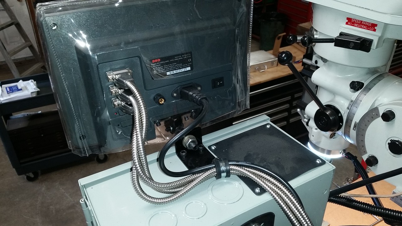
The resolution of the DRO scales is actually .0002". I have to go into the settings menu on the display to change the display resolution. There are one too many zeros right now. I have to spend some time with the DRO manual as it is quite different from the one on the old mill. I'm not sure if I'm a fan of the LCD display, time will tell.
I was struggling with mounting the Z axis DRO scale and power feed stops with the brackets supplied with the kit so I emailed PM and Matt replied with a bunch of pics showing how they do it in their shop. Those pics really helped. I did custom make a couple of bracket parts to make my setup more compact but the mounting concept is the same as PM's. I screwed up when I mounted the Y axis scale, I did it the same way I did my old mill. I noticed how PM does it in the pics that Matt sent then realized why they do it that way. I'm going to change mine and I'll post that change when I do it.
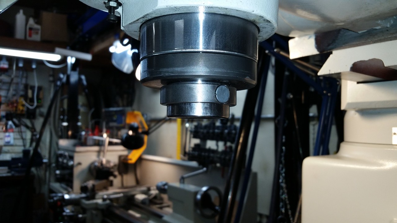
The installation of the spindle tachometer is still on hold until I come up with a better plan. I have already made the parts to mount the sensor and magnet on the quill nose but a couple of things about that setup bother me. Having a magnet that close to the cutting tools is bound to cause problems when it picks a bunch to swarf. The other negative is that the sensor and magnet mounting rings have to move up and down with the quill so keeping the wire harness out of harms way could be a problem. I would rather attach the magnet to the spindle pulley inside the head where it is away from the cutting so I'm working on a plan for that.
The resolution of the DRO scales is actually .0002". I have to go into the settings menu on the display to change the display resolution. There are one too many zeros right now. I have to spend some time with the DRO manual as it is quite different from the one on the old mill. I'm not sure if I'm a fan of the LCD display, time will tell.
I was struggling with mounting the Z axis DRO scale and power feed stops with the brackets supplied with the kit so I emailed PM and Matt replied with a bunch of pics showing how they do it in their shop. Those pics really helped. I did custom make a couple of bracket parts to make my setup more compact but the mounting concept is the same as PM's. I screwed up when I mounted the Y axis scale, I did it the same way I did my old mill. I noticed how PM does it in the pics that Matt sent then realized why they do it that way. I'm going to change mine and I'll post that change when I do it.
The installation of the spindle tachometer is still on hold until I come up with a better plan. I have already made the parts to mount the sensor and magnet on the quill nose but a couple of things about that setup bother me. Having a magnet that close to the cutting tools is bound to cause problems when it picks a bunch to swarf. The other negative is that the sensor and magnet mounting rings have to move up and down with the quill so keeping the wire harness out of harms way could be a problem. I would rather attach the magnet to the spindle pulley inside the head where it is away from the cutting so I'm working on a plan for that.
Last edited:
Sweet mill!! Can’t wait to see the first project from it!
I've had the feeling that the spindle speeds were not as high as indicated on the front panel dial so I used my hand held tach and sure enough 4200 rpm indicated was 3400 rpm actual. Looking at the motor sheave pulley the belt should be right to the outside diameter at the highest speed but it was about a half inch inside that. I had to turn the adjuster for the front sheave rocker arm a full 3 turns to get it so the belt goes within about .060" of the OD of the motor pulley and gives me 4060 rpm max. I could get 4200 but I prefer to keep the belt a little inside the max diameter of the pulley. I tried to get a pic of the belt position on the motor pulley but it's just too dark and hard to see in there for the camera. The rocker arm adjuster screw is on top of the head between the motor and spindle.
You can see the black tape wrapped around the spindle with the small square of reflective tape in this pic


You can see the black tape wrapped around the spindle with the small square of reflective tape in this pic
I went to Lowes this morning and picked up a 4' X 2' piece of 1/8" hardboard and made a pair of table covers so I don't have to sweat about dropping tools on it.


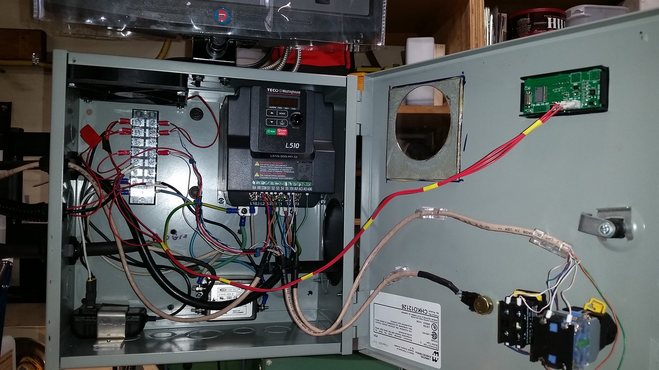
The last bit of work on the VFD was installing a brake switch. With this switch input to S4 of the VFD it will enter "base block" mode as Teco calls it. This mode allows the spindle to coast to a stop so the mechanical brake can stop it as fast as I want and will not conflict with the normal deceleration times.


I fixed my screw up on the Y axis DRO brackets. The way I did it the first time , the X axis power feed would hit the DRO scale bracket before the table achieved full travel to the left in the X axis direction. I had to shorten 1 L bracket and make up a block to mount to the bottom of the saddle. It got me an extra 1.25" of table travel and will prevent accidentally crashing the power feed into the brackets. This is how I did it the first time.
.jpg")


Looking at the motor sheave pulley the belt should be right to the outside diameter at the highest speed but it was about a half inch inside that. I had to turn the adjuster for the front sheave rocker arm a full 3 turns to get it so the belt goes within about .060" of the OD of the motor pulley and gives me 4060 rpm max. I could get 4200 but I prefer to keep the belt a little inside the max diameter of the pulley. I tried to get a pic of the belt position on the motor pulley but it's just too dark and hard to see in there for the camera. The rocker arm adjuster screw is on top of the head between the motor and spindle.
Hmm... interesting. You'll have to show me what you did one day. I've been wondering if my rpm specific harmonic hum might be related to belt setup. Its been a while but I don't recall much mention of this kind of adjustment in PM manual. Does it sound any different now or was it just an rpm thing you were correcting?
Hmm... interesting. You'll have to show me what you did one day. I've been wondering if my rpm specific harmonic hum might be related to belt setup. Its been a while but I don't recall much mention of this kind of adjustment in PM manual. Does it sound any different now or was it just an rpm thing you were correcting?
No real difference in sound except it's not got a top speed about 20% faster. It's a pretty easy adjustment. With your variable speed crank handle all the way to the 4200 rpm max speed setting remove the belt shield and look inside the head to the rear pulley with mill running at full speed. The belt should be all the way to the outer edge of the rear pulley. If it's not you loosen the lock nut on the adjusting screw that sticks up on top of the head between the motor and the spindle. With a flat blade screw driver turn the screw counter clockwise. Turn it about 1/2 turn at a time and observe the belt position after each adjustment. It took 3 full turns to move my belt outward about 1/2". I was monitoring the spindle speed at the same time and got to a full 4200 rpm but turned the screw back clockwise a little to take the belt back in a bit. The mill needs to be running in order to make these adjustments just as it would be when turning the speed crank.
I'll post a video of the mill running through the speed range so you can see if it sounds the same as yours.
This adjustment is not covered in the PM manual or even the Bridgeport overhaul manual I have but it is the only adjustment for belt to pulley contact.
I'll post a video of the mill running through the speed range so you can see if it sounds the same as yours.
This adjustment is not covered in the PM manual or even the Bridgeport overhaul manual I have but it is the only adjustment for belt to pulley contact.
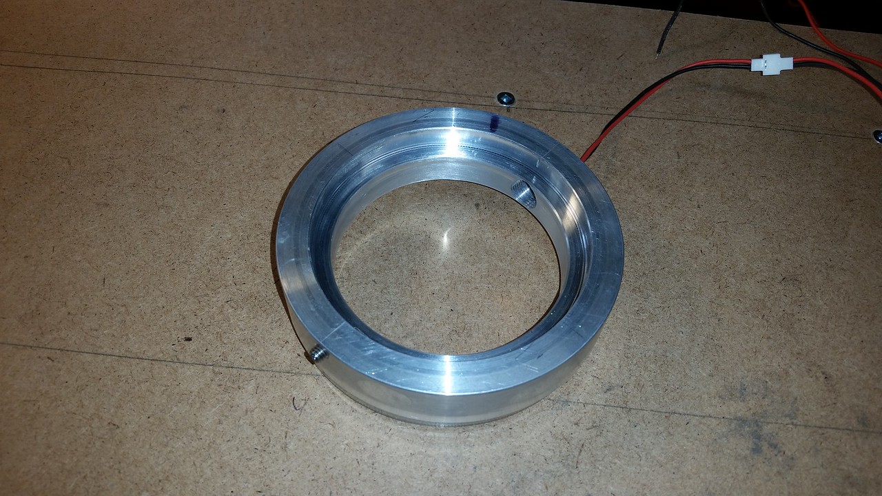
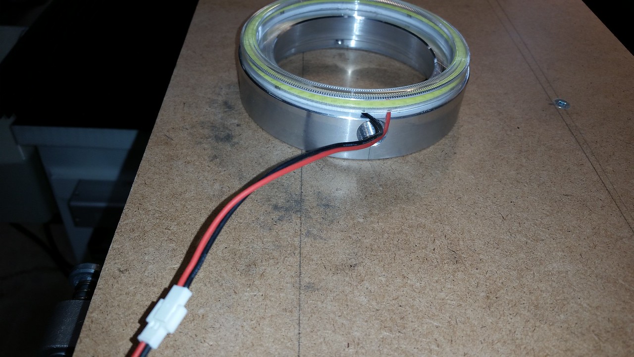
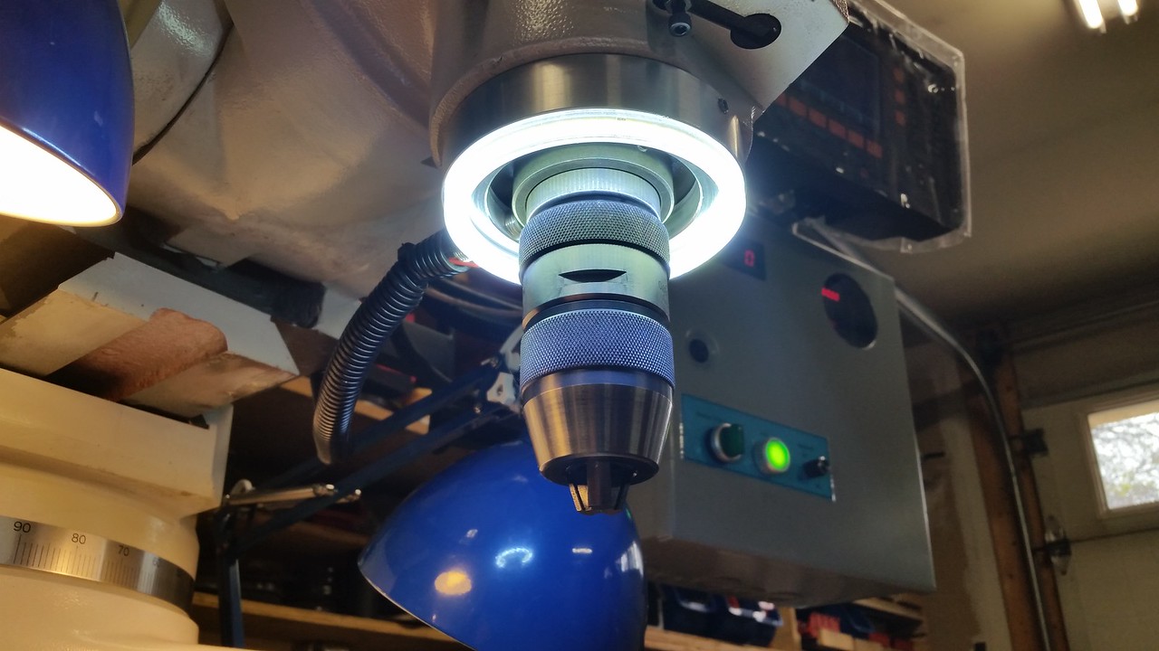
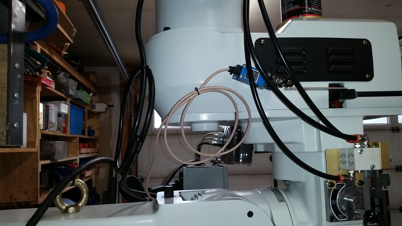
Since I already had the parts machined and a spare digital tach I installed the spindle tach, the design was copied from one made by David Best on the Hobby Machinist forum. I'm concerned that chips will stick to the magnet on the spindle collar and cause problems but it's easy to remove if I don't like it. The collar is cast iron and is a slight interference fit onto the spindle, just a little heat with a heat gun and it slides on but it also has a back up brass set screw holding it. The magnet is attached to the collar with JB Weld the same as I did on my lathe. The sensor ring is aluminum and is a slight interference fit over the nose cap on the quill but also has a stainless M5 set screw holding it in place. The light ring is a 100mm LED halo light from Amazon and is held to the sensor ring with 2 sided tape. I drilled and tapped the sensor ring M12 X 1 so the sensor screws into it and has a jam nut to keep it from moving. There was no plug/wire harness with this tach so I soldered the wires directly to the pins on the back of the display. I shot a short video and you can see it functions fine and the speed agrees with the hand held tach I have. The harness with the tach sensor and light ring wires runs straight out the back of the sensor ring and I covered it with 1/2" split loom for protection. The design is pretty light duty and has lots of potential to fail since the whole thing moves up and down with the quill, time will tell.
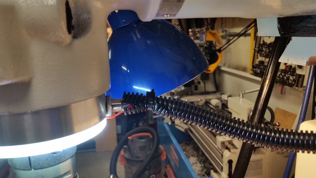
I also did a little cable management, more to come.
I also did a little cable management, more to come.
I was a little skeptical when Matt told me the spindle run out on these mills is .0001 or less. I'm a believer now.
DPittman
Ultra Member
Speaking of cheap tooling...Nice. Mine's the same. Brings a smile to your face. But the downside is you now look at cheaper tooling with a hairy eyeball LoL
I measured the runout on my spindle when I got my milling machine but had forgotten what it measured ,so John's post above encouraged me to check again. I'm doubtful my spindle runout could be as low as seen in the video. Maybe the poor quality indicator? Maybe my setup? A combination of the two factors?
https://youtube.com/shorts/bNOJ6fNBChQ?feature=share
Last edited: