My next CNC project - a PrintNC router

deleted_user

Super User
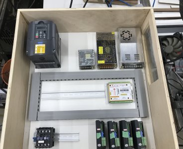
Dropped all the major components into the computer case today.
From top left:
VFD
12v power supply for control board
36v power supply for stepper drivers
(fan which will go above the power supplies)
Four stepper drivers
Control board
I will mount another fan on the bottom of the enclosure to blow across the stepper drivers.
Waiting on wire raceway before I can start wiring in earnest.

View attachment 19961

what brand stepper drivers does the aliexpress store sell?

I think I'm going to start making small purchases locally when I see deals. I'm also going to go with DIN mounted power supplies and make mounted for the stepper drivers. I have a bunch of DIN terminal blocks already
 

DavidR8

Scrap maker
Administrator
Moderator
Premium Member
what brand stepper drivers does the aliexpress store sell?

I think I'm going to start making small purchases locally when I see deals. I'm also going to go with DIN mounted power supplies and make mounted for the stepper drivers. I have a bunch of DIN terminal blocks already
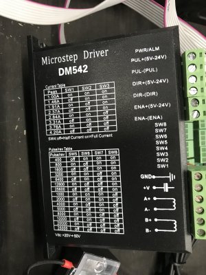
They seem like generic DM542 drivers. I know some folks on the Discord had issues with missing steps and had to replace the kit drivers with drivers from StepperOnline. I hope not to have that problem!
IMG_8037.jpg
 
Last edited:

Dan Dubeau

Ultra Member
Looks like a great project. I'd love to build a small router that size someday too, but not sure where I'd put it. Might have to hang it from the ceiling lol. Looking forward to following along with your build.
 

DavidR8

Scrap maker
Administrator
Moderator
Premium Member
Looks like a great project. I'd love to build a small router that size someday too, but not sure where I'd put it. Might have to hang it from the ceiling lol. Looking forward to following along with your build.
It's funny you mention hanging it from the ceiling as I briefly considered doing that. The router is sized to fit on my 24"x36" welding table as I thought that I could suspend the router from the ceiling when not in use. Now that I have it largely built that's not happening. I sold my surface grinder to make space for the table that I built to hold the router.
Thanks for following along on my CNC newbie adventure!
 
Last edited:

DavidR8

Scrap maker
Administrator
Moderator
Premium Member
Much progress has been made.
I picked up a used PC tower case and have managed to stuff in all the electronics.
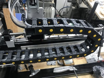
Put on the cable chains and ran all the cabling save for the limit switches. Still figuring out mounting setup for those.
Had a bit of a technical glitch getting connected to my custom made grblHAL motion control board but with the help of the PrintNC community I managed to get that sorted.
T-tracks arrived yesterday so those will get screwed the the frame between MDF strips.
I'll add some pics later :)
 

DavidR8

Scrap maker
Administrator
Moderator
Premium Member
Spent the afternoon in the shop working on the router. Good progress but I didn't hit my stretch goal of a test cut.
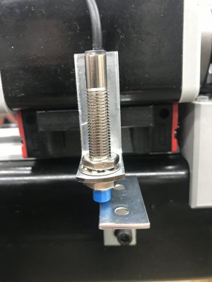
Did manage to get all the cabling pulled, limit switches and triggers installed and tested and the spindle end of the cable is soldered on.
Next step is connect the VFD, cut the spoilboard to fit and make a test cut.

Inductive limit switch and trigger
limit_switch.jpg
X-axis cable chain
cable_chain.jpg

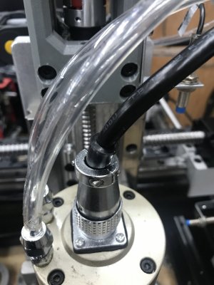
Spindle. Four 16ga wires plus the shielding. I really hate soldering GX connectors.
spindle.jpg
 

DavidR8

Scrap maker
Administrator
Moderator
Premium Member
Well, I've had to make a direction change electronics-wise. Previously I was going to use a custom made grblHAL board and IOSender as control software. I've had many issues flashing the board, proximity sensors that work in the morning and then not work that afternoon without any changes to hardware or software.
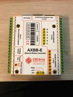
So I decided to move to the UCCNC control software from CNCDrive and their AXBB-E motion control board.
It's proprietary which I have some nervousness about but there is a huge user base and the developers are very responsive.
 

YotaBota

Mike
Premium Member
I was at David's place yesterday and saw this machine. Having pretty much zero knowledge of CNC this for me is the R2D2 of shop machines, really cool to see but I don't know if I would try one. Hell I still have my slide rule from the drafting days.
@David_R8 - are you going to need some kind of strain relief (spring) for the spindle wire? It looks like it could bend over and not take it well.
 

DavidR8

Scrap maker
Administrator
Moderator
Premium Member
I was at David's place yesterday and saw this machine. Having pretty much zero knowledge of CNC this for me is the R2D2 of shop machines, really cool to see but I don't know if I would try one. Hell I still have my slide rule from the drafting days.
@David_R8 - are you going to need some kind of strain relief (spring) for the spindle wire? It looks like it could bend over and not take it well.
Hah, my dad taught me to use a slide rule because well, it was important to know how to use on in case ones calculator died. I was the only person doing grade 12 physics without a calculator because I was not allowed to have one. Alas, now I can barely add two three digit numbers.

Good eye, yes a strain relief is necessary as it's super flexible cable. I'll print something up to connect the cooling hoses and VFD cable to the Z axis motor mount.
 

DavidR8

Scrap maker
Administrator
Moderator
Premium Member
Now it's time to start filling up the enclosure.
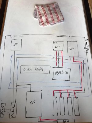
Here is a rudimentary (emphasis on rudimentary!) sketch of how it's going to come together.
dc68de4961b99ab6d385d601c821b580.jpg

From the top left VFD , 5v/24v power supply for the controller and limit switches, 36v power supply for the stepper drivers,
Middle is a row of Dinkle terminal blocks for power distribution and the AXBB-E controller.
Bottom left are 120v breaker, contactor, 12v power supply for the three fans, and the four stepper drivers.
In the top right on the outside are the e-stop, and on/off switches. There may be a potentiometer for VFD speed control. We shall see how controlling the YLang VFD via PWM turns out.
 

DavidR8

Scrap maker
Administrator
Moderator
Premium Member
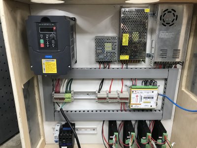
Stole a bit of time at the end of the day to arrange electronics.
I think this layout will work.
The only slightly awkward part is that the wires for the stepper drivers come out of the side of the control board that faces the power supplies. I put the control board on risers so I can run the wires underneath. If it looks messy I’ll just run them out the top and through the wire duct.
495020B1-947C-4B64-9000-CF2443B5943B.jpeg
 

DavidR8

Scrap maker
Administrator
Moderator
Premium Member
Massive progress today. At 10:30am I had the electronics laid out as in the photo in the above post.
At 3 PM I had all the DC and the AC wiring done except for the breaker, contactor, on/off and emergency stop switches wired in. Shortly after 3pm I had movement on all three axes!
Very happy with how the wiring turned out. Super impressed with the UCCNC software.
Just have to drill the bottom left panel for cable glands for power, stepper cables and limit switches. Top right panel will get emergency stop and on/off switches.
enclosure_wired.jpg
 
Last edited:

DavidR8

Scrap maker
Administrator
Moderator
Premium Member
Another big step tonight.
I was struggling with getting the limit switches set up. Wiring was right but they weren't working as expected.
A bit of research revealed some user error in the configuration. a couple of changes in the software config and now all axis have working limit switches and the homing cycle works!
I'm about a hair's breadth away from cutting :cool:
 

deleted_user

Super User
Another big step tonight.
I was struggling with getting the limit switches set up. Wiring was right but they weren't working as expected.
A bit of research revealed some user error in the configuration. a couple of changes in the software config and now all axis have working limit switches and the homing cycle works!
I'm about a hair's breadth away from cutting :cool:
You are lucky that you're an entire continent away.... or I'd be visiting along with a USB stick filled with designs
 

deleted_user

Super User
You are lucky that you're an entire continent away.... or I'd be visiting along with a USB stick filled with designs
I had plans to build a hollow body bass with a nice carved top I wanted to use cnc router to rough out for me... but my joints in my hands got too bad, so I sold my existing bass and amp... but cnc is great for cutting mould pieces for boat models
 
Top