Still a PrintNC, the core of the design is still exactly as intended, the only shift I made was to go with a commercially available motion control board and software. Everything else is exactly as I planned it and true to the PrintNC design philosophy.Is it still a "PrintNC router" or has it morphed into something else?
-
Scam Alert. Members are reminded to NOT send money to buy anything. Don't buy things remote and have it shipped - go get it yourself, pay in person, and take your equipment with you. Scammers have burned people on this forum. Urgency, secrecy, excuses, selling for friend, newish members, FUD, are RED FLAGS. A video conference call is not adequate assurance. Face to face interactions are required. Please report suspicions to the forum admins. Stay Safe - anyone can get scammed.
-
Several Regions have held meetups already, but others are being planned or are evaluating the interest. The Calgary Area Meetup is set for Saturday July 12th at 10am. The signup thread is here! Arbutus has also explored interest in a Fraser Valley meetup but it seems members either missed his thread or had other plans. Let him know if you are interested in a meetup later in the year by posting here! Slowpoke is trying to pull together an Ottawa area meetup later this summer. No date has been selected yet, so let him know if you are interested here! We are not aware of any other meetups being planned this year. If you are interested in doing something in your area, let everyone know and make it happen! Meetups are a great way to make new machining friends and get hands on help in your area. Don’t be shy, sign up and come, or plan your own meetup!
You are using an out of date browser. It may not display this or other websites correctly.
You should upgrade or use an alternative browser.
You should upgrade or use an alternative browser.
My next CNC project - a PrintNC router
- Thread starter David
- Start date
@David_R8 I watched the videos you linked. I don't have a complete comprehension of the CNC mechanics & certainly not the electronics, but I was impressed with various 3DP fixtures & how they integrated the base tube frame build. Look forward to yours as it proceeds to completion. CNC looks like a rabbit hole to oblivion. I dare not stare into the light LOL
To give you a sense of the capabilities of this DIY machine have a look at this:@David_R8 I watched the videos you linked. I don't have a complete comprehension of the CNC mechanics & certainly not the electronics, but I was impressed with various 3DP fixtures & how they integrated the base tube frame build. Look forward to yours as it proceeds to completion. CNC looks like a rabbit hole to oblivion. I dare not stare into the light LOL
This is cutting 1/2 plywood at 8000mm/min.
Dropbox
So a thing happened.
Nothing amazing. But I had to see if everything worked.
No magic smoke from the spindle or VFD
Coolant pump worked.
No broken endmill from crashing into any thing.
But I had my hand on the e-stop the whole time 😱
Despite how much I've learned I now know how little I know and how much more I have to learn.
Still to do:
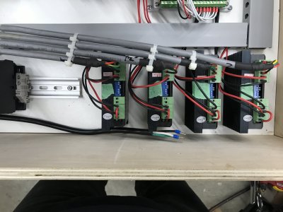
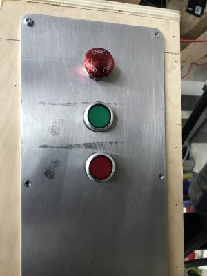
- Wire in contactor, physical e-stop, on/off buttons.
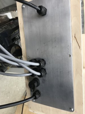
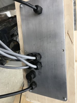
- Drill a boatload of holes in the enclosure for cable glands
- Install enclosure cooling fans (arriving Thursday)
- Route limit switch wiring in enclosure
- Route stepper cables in enclosure
- Finish spoil board attachment
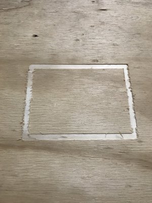

Last edited:
Attachments
Dan Dubeau
Ultra Member
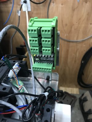
Nicely done. Very neat and tidy!
Thanks Dan. Lots of planning to get everything in and placed in a way that kept line and low voltage separate.Nicely done. Very neat and tidy!
And I had to learn about contactors and latching circuits.
This project has been a tremendous learning experience for me. And I’ve not even started the actual design and machining aspect of it!
Had a big breakthrough with the UCCNC software tonight. I was struggling to get soft limits working. If I homed and then enabled soft limits I would get a message that a soft limit had been reached. Which didn't make any sense to me as the machine was at Zero on all axes.
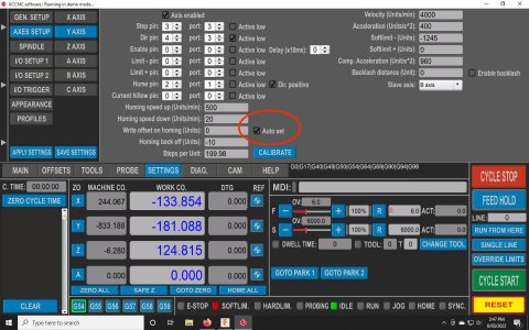
Turns out that homing in UCCNC doesn't automatically zero the machine coordinates. There’s a checkbox on each axis to zero that axis' machine coordinates when homed. Checked them for all axes and entered the travel distances and now my soft limits work. Pretty darn happy about that!
Turns out that homing in UCCNC doesn't automatically zero the machine coordinates. There’s a checkbox on each axis to zero that axis' machine coordinates when homed. Checked them for all axes and entered the travel distances and now my soft limits work. Pretty darn happy about that!
Last edited:
Another big progress step.
I was struggling to get my AXBB-E board and UCCNC software to control my VFD which powers the spindle.
A bunch of research gave me some direction.
In the end I used the following connections:
VFD terminal AXBB-E Terminal
VI ---> AO1
GND ---> 5V0 (from 5V power out not 5V0 Port 1)
XGND ---> 24V0 (I took this from my 24V common)
FWD ---> Pin 7, Port 1
In the UCCNC software:
Spindle config screen: set "PWM Pin" to Pin 7, Port 1
I/O Setup screen: set "Spindle PWM -> analog ch" to 1
On the VFD:
Parameter 00.01 set to 1
deleted_user
Super User
I'm loving this thread... and how you've included sufficient bread crumbs for me to follow on identical build
Happy to try and keep it well documented. Good documentation was always a thing for me and this project has proven just how important it is. The manual for the AXBB-E board is good but the UCCNC manual could use a good dose of explaining what settings do.I'm loving this thread... and how you've included sufficient bread crumbs for me to follow on identical build
I would never have figured out the soft limit thing had someone not explained two things:
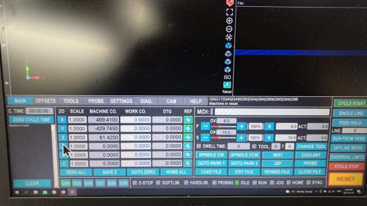
1) that a different screen set was available that showed both work and machine coordinates at the same time. This let me see that homing zeroed the work coordinates but not the machine coordinates.
This is the screen set that I had to find. This is a shot after homing. Notice the Work Co. are zero but the Machine Co. for Y is -429.7450.
So when I enabled the Y axis soft limit of -264, the controller immediately said "Whoa there big fella, you're already out of bounds, you ain't going anywhere!" (or something that 😉)
2) what the "Auto Set" checkbox did. As soon as I checked this box and homed the machine all the coordinates set to zero which allowed my Y soft limit of -264 work. (This is not a screen shot of my software but an example)
Last edited:
Definitely both!Looks like a wahoo moment!!!
You're either over designed or under tooled. 😉
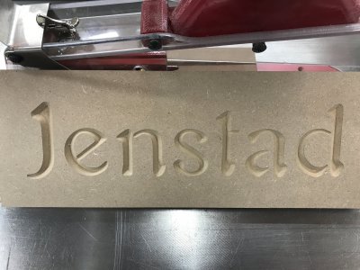
I tried out vcarving for the first time.
Went ok in my books.
Tried using my corner finder today and ran into a bit of a problem.
When I tried to clip on the magnet that is connected to the DC0 I got a spark.
Eventually found a proximity sensor with an internal short sending 24v+ to the sensor body thus energizing the entire steel mass so connecting the DC0 lead was dead short and shut down the software.
New sensor is on it's way.
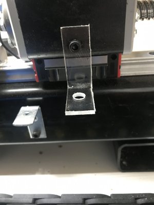
In the mean time I made a quick sensor mount out of acrylic to isolate the sensor from the frame.
Went ok in my books.

Tried using my corner finder today and ran into a bit of a problem.
When I tried to clip on the magnet that is connected to the DC0 I got a spark.
Eventually found a proximity sensor with an internal short sending 24v+ to the sensor body thus energizing the entire steel mass so connecting the DC0 lead was dead short and shut down the software.
New sensor is on it's way.
In the mean time I made a quick sensor mount out of acrylic to isolate the sensor from the frame.

I'm a bit speechless to be honest!Your a lucky Son of a B!
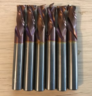
I had to look up 'compression' end mill. Is this a preferred weapon of choice for certain materials like wood or composites?
 www.stepcraft.us


