• Scam Alert. Members are reminded to NOT send money to buy anything. Don't buy things remote and have it shipped - go get it yourself, pay in person, and take your equipment with you. Scammers have burned people on this forum. Urgency, secrecy, excuses, selling for friend, newish members, FUD, are RED FLAGS. A video conference call is not adequate assurance. Face to face interactions are required. Please report suspicions to the forum admins. Stay Safe - anyone can get scammed.

Micro-controller controlled Pneumatic Power Draw Bar

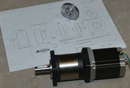
So time to make the two adapters for the stepper motor planetary drive so I can turn a socket.
1662854344371.webp


Start with the raw materials. In this case 2" steel bar. Two pieces.
RawAdapterMaterial.jpg


Dew point has risen in the shop by one degree since it's also pretty warm outside.
 
Since I'm getting forgetful I thought I'd make up a drawing that outlines the machining operations for turning the socket driver part of this hub. (The blue one).

If it seems like I'm doing something dumb please do let me know.
 

Attachments

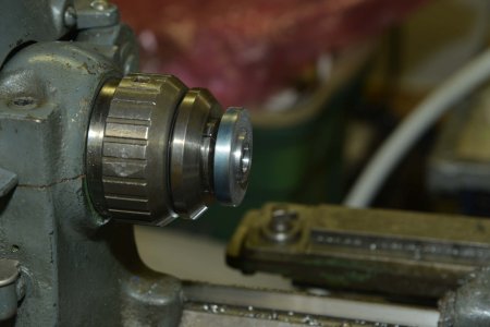
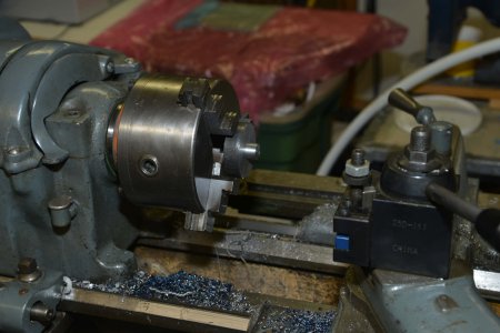
This evening my wife threw the stuffies around so our dog was distracted and wouldn't cry at the shop door so I had a few hours to play. This HRS sure tears and doesn't turn well. I'm even using carbide and 0.025" deep cuts

1. Flatten both sides of the disk I cut off.
2. Turn a 9/16" hub and then mount in collet
3. Turn to the correct width and create the registration edge
4. Looks almost like the drawing.

The 14mm hole depression on the one side is just in case the motor shaft (also 14mm) has to protrude a tad.

Next chance to do something will maybe be Wednesday and then I can do the other hub which will have the 14mm hole and 5mm key. Need to make a broach holder yet.

Final operations will be the 4 holes drilled 5mm in this hub and threaded for 5mm screws in the second hub and cutting the 9/16" round hub into the 3/8" socket driver.
 

Attachments

  • HubSocketDriver-1.jpg
    HubSocketDriver-1.jpg
    142.3 KB · Views: 9
  • HubSocketDriver-b.jpg
    HubSocketDriver-b.jpg
    129.8 KB · Views: 9
  • HubSocketDriver-a.jpg
    HubSocketDriver-a.jpg
    181.3 KB · Views: 9
Since I'm getting forgetful I thought I'd make up a drawing that outlines the machining operations for turning the socket driver part of this hub. (The blue one).

If it seems like I'm doing something dumb please do let me know.

Sorry I didn't see this earlier. We had a nephews wedding this weekend. I just looked at your drawing now. It looks good to me. Very cool to do an order of ops like that.

My only question is the shallow drilled hole. Why so shallow? Also, why did you choose to drill? For shallow holes like that, I'll often use an end mill because it creates a flat bottomed hole that can then be bored to size.

Obviously, if the bottom of the hole doesn't matter, a drill is fine. I'm really only pointing out that an endmill can be used to achieve a flat bottomed hole.
Shallow because I didn't want to take away strength from the 3/8" driver part.

Funny you should mention that. After the drilling and realizing the boring wasn't going well, I took a 1/2" mill and made the initial hole deeper. Then opened it out to 14mm. It wouldn't have had that dimple. I'll change my instruction sheet.

Other part won't matter because the hole is all the way through.
 
Haven't added the adapter or even a socket to the assembly yet but it's clear the current one for moving the impact wrench up and down is totally not what I need.

Going to have to rethink this I think. Push the motor assembly up from the base rather than down from the top since the planetary mount face is at the other end of the butterfly wrench.

The attached pdf is the 3D type that you can click on and then rotate to look at it from all angles but you'll have to download it to get that feature. Doesn't do it from the web browser.
 

Attachments

Back to this thread from the Broach and Broach guide examples.
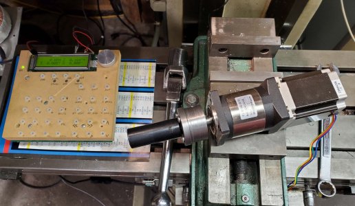
The socket driver is complete
SocketDrive-1.jpg
and fits onto the motor+planetary drive perfectly.
SocketDrive-2.jpg
I tightened up the draw bar with a torque wrench to 220 inch-lbs which is about 18 ft-lbs. That's about what I end up setting it to with a wrench. I put a wood working clamp on the motor so I could hold onto it and then jogged counter clockwise. The assembly had no trouble loosening it.

Max step rate from the ELS is 20,000 steps per second. Set up to have 1600 steps per rev and turning the 25:1 drive means it takes 40,000 steps to make one turn of the socket. That's two seconds per rev from the motor turning 750 RPM which is about max before a stepper starts to see torque drop off to the point of being useless.

But I think this will work.
A few things though:
I made the 3/8" drive nub the same length as the torque wrench or ratchet I really should have made it longer. The hole in the socket for capturing the drive isn't in the right place. So it looks like I should make a new one with a longer piece.

Backlash on the mill is still an issue even though I believe I have the correct amounts into LinuxCNC. It doesn't locate the center of a part using my touch probe as well as I'd like.

Oh and cutting the soft steel nub was done at 1150 RPM, F4 feed rate and 0.015 depth of cut over the length of the nub done with a 0.25" ball mill.

Now to start on a new frame design that will hold this motor drive assembly.
 
Turns out it wasn't only backlash. I either forgot or assumed that my probe was calibrated. Turns out after I went through the calibration procedure I found it was out by about 0.010".

ProbeSetup.webp

Once I did that I put a 1-2-3 block into the vise and used the LinuxCNC VersBy screen to find the center of the 1-2-3 block. From the LinuxCNC perspective the edges are now in the correct spot. From the Shumatech DRO the Y is good but the X is still out about 0.002". I'm guessing that the backlash adjustment for LinuxCNC is out a hair.

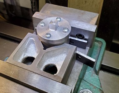
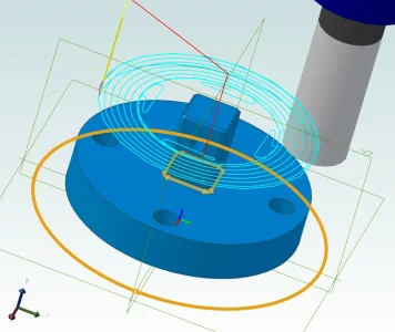
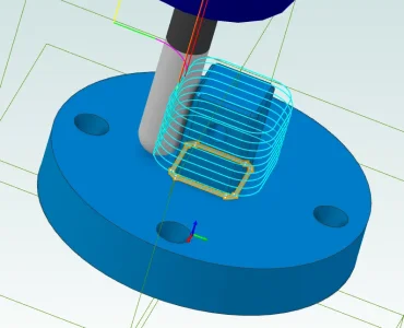
Time to do some more testing there but for now I've clamped a piece of casting sprue turned to just over 2" into the vise. I'll see how the CNC approach works on this test piece.
 

Attachments

  • RoughingHub.webp
    RoughingHub.webp
    81 KB · Views: 1
  • FinishingHub.webp
    FinishingHub.webp
    41.9 KB · Views: 1
Time to do some more testing there but for now I've clamped a piece of casting sprue turned to just over 2" into the vise. I'll see how the CNC approach works on this test piece.
I did try the aluminum but this casting sprue is so soft and gummy and I was running the CAM generated for steel, so way too slow. I still think it's easier to turn a hub on the lathe first and then square that.

MillingSocketDriver.jpg
 
Because the 3/8" drive hub is a bit short it's been suggested that I just weld to the top of it and built it up a bit. Then machine it back to size. That should give me the support for the retaining hole and screw.

Today I just spent tidying up and vacuuming up chips. The pile of steel ones on the lathe and mill were way to sharp to leave lying around.
Gotta say my world has been getting better through deeper shop cleaning.
Also, moving to better-machining steel has been helpful. The difference between 12L14 and 1018 is night and day. The 12L14 makes chips! Just like the books claim! I have some lovely 1018 razor slinkies from before figuring that out.
 
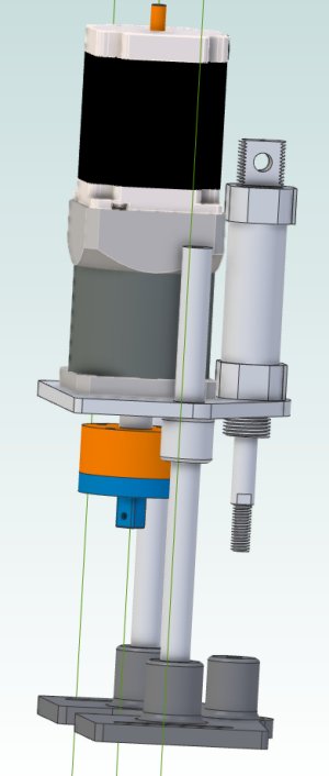
A bit of progress last night. I've spaced the guides further apart so the motor assembly fits between. Flipped the air cylinder around so the ram will be fastened to the base rather than to the upper bracket. Still need to design a new upper bracket to steady the guides and fit around the motor.
 

Attachments

  • PDB-Rev1.jpg
    PDB-Rev1.jpg
    30.3 KB · Views: 2
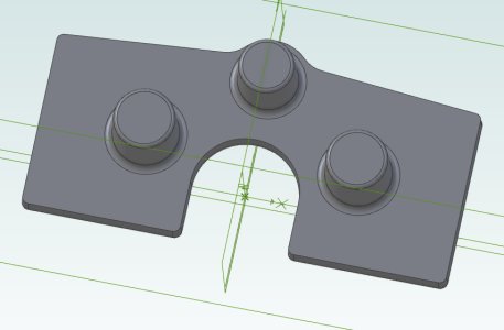
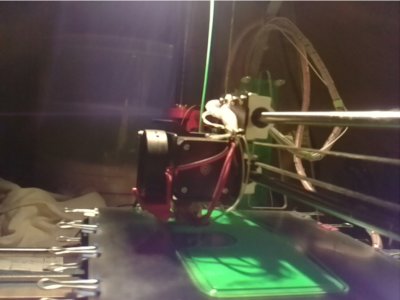
Scale the drawing up by 1% to handle shrinkage. Always a bit of a crap shoot, Add 3 degrees draft so it will pull from the sand. Remove all the holes and slots. Then 3D print.

Still need to do the motor mount bracket pattern and print that. Then fill, prime, sand and paint. And wait for a bit damper weather before I pull the furnace out onto the driveway and cast.
 

Attachments

  • PDB_PatternDrawing.jpg
    PDB_PatternDrawing.jpg
    32.6 KB · Views: 3
  • PDB_BasePrinting.jpg
    PDB_BasePrinting.jpg
    55.5 KB · Views: 3
And wait for a bit damper weather before I pull the furnace out onto the driveway and cast.

On the driveway???

I have this mental image of you on the driveway with the furnace running and the whole neighbourhood sitting across the street in lawnchairs watching, and wondering when you are gunna put the burgers on. ;)
 
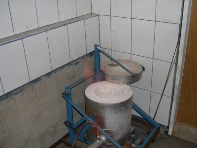
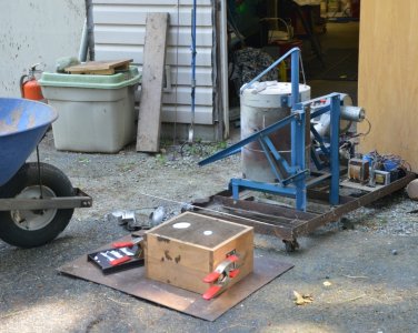
Once I get the fume hood made (Project #42) I can go back to casting indoors. For now the hose to the Natural Gas line is long enough for me to wheel the assembly outside the door. The vehicle is parked in such a way and trees are along the driveway so that from the road nothing can be seen.
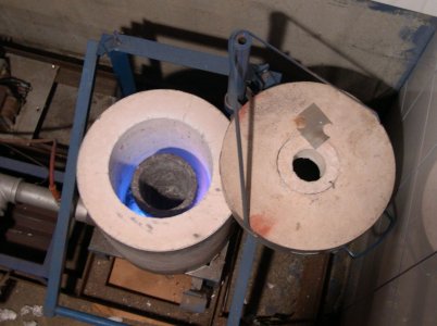
First photo is when the spark plug has ignited the gas but the fan is only turning slowly.
Second is after ignition the fan spools up to melting speed, the flame pulls into the furnace and spins around the crucible.
Third is pour is complete, ingots made from left over metal, furnace is closed and back on slow speed with gas solenoid now off.

Inside the shop that corner with the furnace is lined with the cement board used for shower stalls, then ceramic tiles. That's also my welding corner.
 

Attachments

  • PreFanLightup.jpg
    PreFanLightup.jpg
    129 KB · Views: 9
  • BlowerOnWithCrucible.jpg
    BlowerOnWithCrucible.jpg
    238.6 KB · Views: 9
  • D8X_5535-ACServoMountPoured.jpg
    D8X_5535-ACServoMountPoured.jpg
    108.5 KB · Views: 9
Once I get the fume hood made (Project #42) I can go back to casting indoors.

You are truly a man of many talents. From S100 to ELS to casting. I am truly impressed.

I enjoyed the neighbourhood image though......
 
Back
Top