• Spring 2024 meetup in Calgary - date Saturday, April 20/2024. discussion Please RSVP Here to confirm and get your invitation and the location details. RSVP NOW so organizers can plan to get sufficient food etc. It's Tomorrow Saturday! you can still RSVP until I stop checking my phone tomorrow More info and agenda
  • We are having email/registration problems again. Diagnosis is underway. New users sorry if you are having trouble getting registered. We are exploring different options to get registered. Contact the forum via another member or on facebook if you're stuck. Update -> we think it is fixed. Let us know if not.
  • Spring meet up in Ontario, April 6/2024. NEW LOCATION See Post #31 Discussion AND THE NEW LOCATION

Micro-controller controlled Pneumatic Power Draw Bar

jcdammeyer

John
Premium Member
This is a more appropriate place to continue the thread that started out asking about coil springs.
https://canadianhobbymetalworkers.com/threads/coil-springs.3876/page-2#post-51519

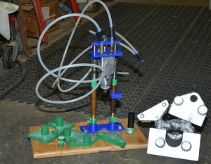
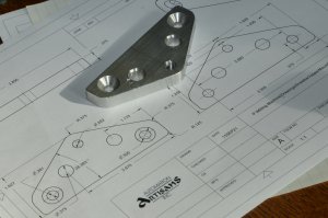
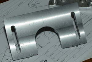
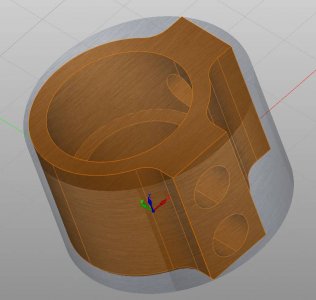
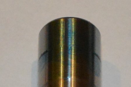
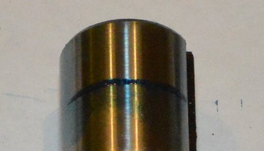
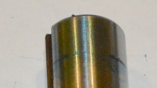
Finally got around to casting the patterns today.

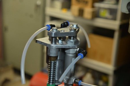
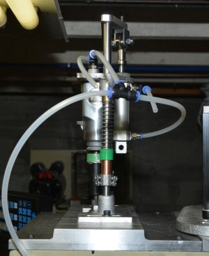
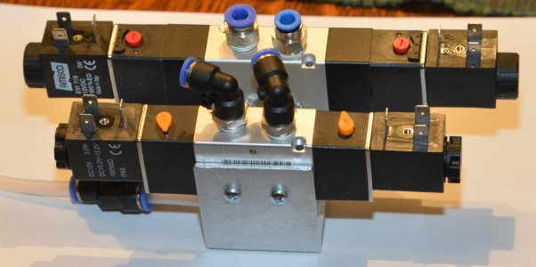
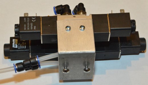
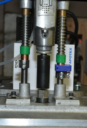
Also since it appears that my AliExpress ordered pneumatic valves have been cancelled by the sender (waiting for credit now) I bit the bullet and went over to Princess Auto and picked up the 5 way 2 position valve to run the cylinder as I've not been able to get it to move while sharing air with the butterly impact wrench.
PA 5 Way 2 Position
The down side is it's truly binary in that when one coil is energized the valve moves over and stays there as does then the cylinder. The other coil has to be energized to move it in the other direction. So the coils don't need to have power continuously. But it needs two outputs.
 

Attachments

  • Castings.jpg
    Castings.jpg
    245.1 KB · Views: 36

jcdammeyer

John
Premium Member
It needs to be reduced in thickness by another 0.03" or so which will remove some more of the bigger imperfections but I'm still having issues with porosity. It's not that it matters as the part is more than strong enough and I still have to mount and run the G-Code to profile it and drill the holes.
Porosity.jpg
My source material is scrap extrusions and whatever aluminium I have lying around. I use a degassing compound which creates lots of bubbles and brings a lot of crap to the surface of the silicon carbide crucible. This was poured at 710C. Surface was milled at 5 ipm, 400 RPM, 0.01 depth of cut with a 4 carbide insert facing mill. And yet there's still the tiny little bubbles.

Silky smooth though.
 

jcdammeyer

John
Premium Member
What degassing compound are you using?
It's pink. The container is marked "from Joe". It's so long ago I don't even remember where I got it. I did have a container of pool chlorine which is supposed to remove much of the dissolved hydrogen gas that expands as it cools. But it sat and absorbed moisture and one day I noticed the plastic container had expanded, cracked and spread goopy white stuff all over the bench. That's when I started also having more rust problems but that's another story.

My raw material is crap. As I said, extrusions that are also dirty. Ideally I should probably first make ingots properly degassed and clean. And then start with those. This pour was a mix of ingots from 10 years ago and extrusions and an old sprue plus some stamped 1/8th sheet aluminium.

The material/casting is more than strong enough for what it's supposed to do. But it would be nice to be able to take this crap and make a pristine, if soft and hard to machine, casting.
 

jcdammeyer

John
Premium Member
Well after screwing up the casting because the X axis lost position between homing I've now converted the entire machine to Bergerda AC servos. Now my zero position for the part is repeatable.
I had a small piece of 3/8" flat aluminium bar stock so I used that to make the part that was originally going to be cast.

Depth of each pass was 0.050" with 14.6 ipm and spindle RPM 1000 turning a 1/2" two flute center cutting end mill. The two sloping sides were done with the full 1/2" cutter with the two vertical and the bottom was no more than about 1/8" or os. I think the chatter and rough marks are due to backlash as it's following the slope.

I really don't know. This is where my amateur status shows through. No idea if it's feeds, speeds, spindle rpm, cutter quality (Busy Bee Tools) or even spindle bearings.
 

Attachments

  • UpperMountPlate.jpg
    UpperMountPlate.jpg
    1.4 MB · Views: 13

Tom O

Ultra Member
Was it just a roughing tool path ( with .010 left for finishing ) or did you follow up with a finishing pass to smooth it out
 

jcdammeyer

John
Premium Member
No I didn't do a finishing pass. Have to figure out how to get the MecSoft CAM to do that. Probably a separate G-Code operation.

However the next step was facing off the bottom of the base casting which went really well. After that the mounting slots. And there you can see how the X axis gets pushed as the 1/4" end mill bites into the metal and then stays offset by the 0.027" backlash.

Unfortunately on this mill there is no way to remove it. I'd have to create a new bronze ACME anti-backlash adjustable nut. I don't think it's worth the effort compared to fitting a proper ball screw.
 

Attachments

  • BasePlateBottom.jpg
    BasePlateBottom.jpg
    1.5 MB · Views: 8

jcdammeyer

John
Premium Member
Things are progressing. Made the second spring collar tonight. Really must refit the mill with ball screws. It's always been find to position and drill using the DRO and scales but unless I somehow close the loop to the scales with LinuxCNC the open loop and terrible backlash leave a pretty ugly surface finishing holes don't line up as well because the CNC doesn't always approach from the same direction.

Tomorrow the weather forecast is for no rain so I can finally cast the plate that the draw bar system will bolt onto.

So here are a few more pictures.
 

Attachments

  • DrawBarMech-1s.jpg
    DrawBarMech-1s.jpg
    109 KB · Views: 9
  • SpringCollar-CAD.jpg
    SpringCollar-CAD.jpg
    39.3 KB · Views: 9
  • SpringCollar-2.jpg
    SpringCollar-2.jpg
    193.5 KB · Views: 9

jcdammeyer

John
Premium Member
So I poured the milling machine spindle cover plate which will hold the drawbar assembly. The original from House of Tools was just sheet metal made to look like a casting. SpindleCoverPlate-2.jpg

One slight side effect. Forgot how long the furnace had been on and reached under to pullout a metal ring that was in the exhaust flow. Some cold water, a couple of bandaids and finished the pour.
SpindleCoverPlate-1.jpg

Next some machining, trimming the edges to the correct width, creating the slots and holes and taking care of a bit of sag in the top part of the casting. This is the bottom and the slot is in the back to match up to the motor mount plate.
SpindleCoverplate-4.jpg

Next step is make a slightly longer draw bar with a single 9/16" hex nut at the top. Enlarge the two mounting holes and tap them 6mm. And drill the 4 holes for the 6mm hold down screws onto the head casting. Might need to add a couple more hold downs too.
TrialFitOnSpindleCover-1.jpg

And then shorten the 1/2" copper pipe so the socket is just above the draw bar. I may just have a power drawbar before Christmas...
 

6.5 Fan

Ultra Member
Premium Member
For a burn i keep vitamin E capsules in the fridge, smear some of the E liquid on burn as soon as possible. Otherwise project looks good.
 

jcdammeyer

John
Premium Member
Thanks. I was lucky. The skin remained intact and each has a big bubble of skin covering fluid protecting the burn while it heals so as long as I keep it bandaged it should be fine. I keep a pharmacist in house just for these sort of things. She burns herself on the oven way more often than I do. Been a long time since I grabbed a soldering iron incorrectly too.

The key thing is now that I have the system on the stand I can measure how much to remove from the two 1/2" rods and the water pipe spacers so the socket clears properly but also is down as it starts turning. Although I can delay that now with software since I'm now controlling the cylinder separately from the butterfly wrench. They switch off at the same time. Or more precisely the up valve will go on at the same time as the air to the wrench is switched off.

But for the other direction I think I will introduce a delay so the socket goes down first and then is spun for 2 turns before the off event.
 

jcdammeyer

John
Premium Member
Finished milling and threading the cylinder link. U-Joint-8mm.jpg That was an interesting exercise.
It moves the butterfly wrench closer so I found a few short pieces of copper pipe. There's just enough spring tension to push it back up and I plumbed it for now to use the same air for the cylinder and the wrench so it's not very predictable the way it will be when the micro-processor controls the cylinder and wrench separately.

But holding the air hose against the open tube showed that it can do a decent job to push down and either tighten or loosen an R8 tool depending on how I arrange the tubes. Still have to drill, tap and countersink the base casting (and clean up the edges so the wrench fits if I want to use it.
Baby steps.
 

Attachments

  • TrialRun-Front.jpg
    TrialRun-Front.jpg
    490 KB · Views: 2
  • TrialRun-LHS.jpg
    TrialRun-LHS.jpg
    463.7 KB · Views: 2
  • TrialRun-RHS.jpg
    TrialRun-RHS.jpg
    494.3 KB · Views: 2

jcdammeyer

John
Premium Member
Made a U shaped bracket to hold the two pneumatic valves. This will screw to the head side cover which I normally never remove.
Used the probe to find the corners and then move to the appropriate positions to spot and then drill the holes. Same with the holes in the bottom for mounting to the cover. Didn't use the power tapping because my 5mm spiral tap doesn't fit in the tap collet meant for a 5mm tap. So just a pointed piece in the spindle guiding the tap. Do like those spiral taps for aluminium.

Anyway. Successful day. Not nearly as many mistakes as I usually make. The longer valve runs the Butterfly Wrench with a center CLOSED position. The shorter one is a dual position latching valve because the type I wanted was not carried by Princess Auto. Actually it was but what they have in stock is NORMALLY OPEN.

So I had to add an extra output to move the cylinder up and down. The springs therefore aren't really needed but help with keeping it up out of the way when air is shut off.
 

Attachments

  • ValvesOnBracket-1.jpg
    ValvesOnBracket-1.jpg
    1.2 MB · Views: 2
  • ValvesOnBracket-3.jpg
    ValvesOnBracket-3.jpg
    1.3 MB · Views: 2

jcdammeyer

John
Premium Member
Here's a link to a very short video showing the power drawbar progress.

Press unload button and cylinder goes down first. Then wrench turned on max 1 second. Then both wrench turned off and up valve switched on to lift wrench out of the way. Sure does move fast. Might want some rubber stops to absorb some of the shock.

First test of pneumatically controlled power draw bar.

Only one tiny little problem happened when I put it all on the mill along with the RPM count sensor. Nothing in the quill. Just spinning the draw bar.

I think I damaged the top part of the spindle from possibly the drawbar spinning around loose. Most of my R8 tools will no longer slide up into position. There have always been some that are a tad tighter than others and I put that off on tolerances in the far east R8 collets. But now I can only find one that fits and it's tight.

I put bluing on it and pressed it in and then pushed it out. The photos show 3 different angles and that in some places the bluing has been pushed down and in others not touched. Almost as if the end of the spindle where the collet goes in is not round.

Not sure how to fix this.

I knew I had to replace the draw bar anyway. It's a bit smaller in diameter than the original and 5mm too short with the thick washer at the top. And the impact wrench in no time loosened the double nuts (which I expected). I wouldn't think that the drawbar threads can even touch the surface that registers the collets. And the drawbar isn't marked up. Threads look fine.

Ideally a reamer to clean it out. But the registration pin is in the way so I think the spindle has to come out.
 

Attachments

  • DBAR-FIT-1.jpg
    DBAR-FIT-1.jpg
    303 KB · Views: 2
  • DBAR-FIT-2.jpg
    DBAR-FIT-2.jpg
    275.4 KB · Views: 2
  • DBAR-FIT-3.jpg
    DBAR-FIT-3.jpg
    276.5 KB · Views: 2

jcdammeyer

John
Premium Member
I cleaned up the entrance to the parallel 0.950 diameter section of the spindle with a small drump sander held in an extension and manipulated by hand. After that the collets all went in really easily.

Tried again with air on the impact wrench. Litterly twisted a off roll pin that was through the nut and the drawbar shaft. When it works, it works well. But I'd say at the moment it works 1 of 5 tries. Until it broke the pin.

Looks like I have to make a new drawbar. Or somehow weld the nut on so it will stay.
 

kevin.decelles

Jack of all trades -- Master of none
Premium Member
My draw bar on my 6x26 is in the same state. Roll pin keeps breaking. Going to take care of that by welding or solid draw bar.
 

jcdammeyer

John
Premium Member
My draw bar on my 6x26 is in the same state. Roll pin keeps breaking. Going to take care of that by welding or solid draw bar.
I used a pretty small roll pin (#40 drill for the hole) on the 9/16" nut. At about 80 PSI the impact wrench had no trouble breaking it. Also realized that the wrench didn't go down far enough so the draw bar climbed up and had trouble ejecting the R8. I've adjusted that and had better success but if the socket sticks at all then the socket is left behind. I do have a set screw in the socket that could clamp onto the driver but I think I should probably dimple the square driver so the set screw hooks it in place rather than holds it with pressure.

Not ready to do a video yet.
 

jcdammeyer

John
Premium Member
One I realized by thinking outside the box that if I used the lathe with traveling steady I could reduce the drawbar enough so it would fit through the back of the rotary table since I didn't have a 14mm 5C collet for the spin indexer. Not only that the drawbar isn't exactly straight so it binds a bit making it difficult to finger tighten. The new thinner 13.5mm drawbar no longer binds and fits through the table so it can be clamped.

Easy then to index and cut the 6 flags from the 22mm square head into 19mm (18.6mm compared to 18.75 for a nut I had on hand) hex head.

Problem though. If the socket isn't perfectly lined up it just stops at the top and essentially jams. I see nuts have a bit of a bevel. What sort of shape do I need to put on the top so the socket is uncomfortable out of position and _wants_ to turn to line up with the nut. Do I make it spherical? Or angle from the center of the flat top edge in both directions towards the nut corners. So the flat on the inside of the socket follows a ramp towards the corner.

If that makes sense?
 

Attachments

  • ModifiedDrawbarNut19mm.jpg
    ModifiedDrawbarNut19mm.jpg
    946.9 KB · Views: 4
  • DrawbarShaftResized.jpg
    DrawbarShaftResized.jpg
    1.4 MB · Views: 4
  • HexHeadOnDrawbar.jpg
    HexHeadOnDrawbar.jpg
    1.7 MB · Views: 3
  • DrawbarSquareHead.jpg
    DrawbarSquareHead.jpg
    1.4 MB · Views: 4
Top