Micro-controller controlled Pneumatic Power Draw Bar

jcdammeyer

John
Premium Member
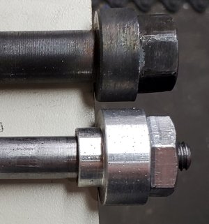
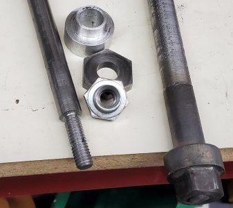
No matter what I do to the top of the draw bar the 12pt socket still can jam onto the draw bar head. The head is just too soft.
DrawbarJammed.jpg
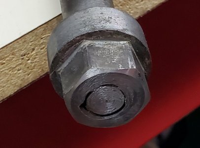
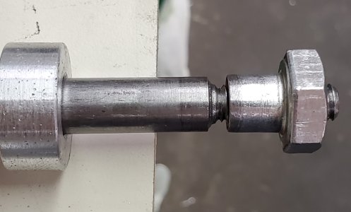
And I now see that the head was either welded or glued or threaded onto the draw bar shaft.
DrawbarHead.jpg
The metal is very soft so I tried heating it to orange/yellow with the torch and quenching in water. That didn't work. Still soft. I can pull down against the springs by hand (no air pressure attached) and just that action can jam the socket onto the head.

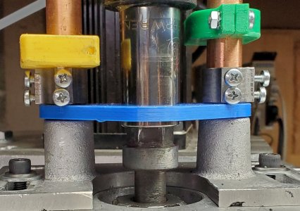
To prevent rounding the nut and random carving of the head I added a second hall sensor on the other post and magnet attached to the cylinder body to sense when the draw bar socket is down all the way. Tweaked the software to deal with that and if not all the way down then go back up and blip wrench and try again. Problem there is now that the socket is sticking to the draw bar head it brings the unloaded draw bar up with it so that's not working. If the drawbar is attached to a collet then the socket can be pulled really hard. It was coming off but I've fixed the retainer so that works better.

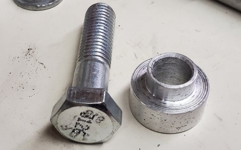
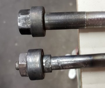
Next step is to somehow attach a 12mm bolt from Home Depot (with the 19mm head) onto the draw bar. It's definitely harder than what's there. If that doesn't work I'll look at some oil or water hardening stock and make something really hard.
 

jcdammeyer

John
Premium Member
So I've cleaned up the draw bar head yet again to look as much as possible as a standard 12mm bolt and I also turned a spacer to bring the bolt up high enough so that the head is in reach of the draw bar at the lowest position.

Using the bolt and spacer I cannot, no matter how hard I try, get the bolt to stick in the socket. On the third try once again the draw bar did get stuck. The teeth in the socket just deform/deflect the metal enough to cause it to stick.

The spacer is aluminum. (A piece of left over sprue from casting). In real life it would be steel. The problem is how to connect the draw bar to this bolt and the steel spacer.

Ideally I'd buy a piece of 1" diameter water or oil hardening steel and create a combination bolt head and spacer like what appears to be on the original drawbar. But something that is actually hard after heating and quenching. I did try that with the original draw bar bolt but it didn't get any harder or softer after heating and quenching.

It looks like the original was threaded onto the shaft but I can't see how they locked it on. Heating to orange and quenching should have broken any sort of loctite bond.

I don't want to weld directly onto the bolt head so that the hardness isn't changed. One idea I had is to drill and tap say 5/16" through the middle of the bolt cutting off the 12mm threaded part. Then take another drawbar I built and thread the end 5/16. to screw into the bolt. Then slide on a spacer without the shoulder. Maybe even with a V groove on the bottom. Weld the junction between the bolt, the drawbar and the spacer and build it up enough so that when turned down becomes that shoulder to center the bar in the spindle. That also allows the lathe to make the bottom face and shoulder of the drawbar concentric to the rest of the drawbar and spindle.

Suggestions?
 

Attachments

  • DBAR-FIT-6.jpg
    DBAR-FIT-6.jpg
    595.3 KB · Views: 5
  • DBAR-FIT-5.jpg
    DBAR-FIT-5.jpg
    665.8 KB · Views: 5
  • DBAR-FIT-4.jpg
    DBAR-FIT-4.jpg
    827.1 KB · Views: 5

Susquatch

Ultra Member
Administrator
Moderator
Premium Member
So I've cleaned up the draw bar head yet again to look as much as possible as a standard 12mm bolt and I also turned a spacer to bring the bolt up high enough so that the head is in reach of the draw bar at the lowest position.

Using the bolt and spacer I cannot, no matter how hard I try, get the bolt to stick in the socket. On the third try once again the draw bar did get stuck. The teeth in the socket just deform/deflect the metal enough to cause it to stick.

The spacer is aluminum. (A piece of left over sprue from casting). In real life it would be steel. The problem is how to connect the draw bar to this bolt and the steel spacer.

Ideally I'd buy a piece of 1" diameter water or oil hardening steel and create a combination bolt head and spacer like what appears to be on the original drawbar. But something that is actually hard after heating and quenching. I did try that with the original draw bar bolt but it didn't get any harder or softer after heating and quenching.

It looks like the original was threaded onto the shaft but I can't see how they locked it on. Heating to orange and quenching should have broken any sort of loctite bond.

I don't want to weld directly onto the bolt head so that the hardness isn't changed. One idea I had is to drill and tap say 5/16" through the middle of the bolt cutting off the 12mm threaded part. Then take another drawbar I built and thread the end 5/16. to screw into the bolt. Then slide on a spacer without the shoulder. Maybe even with a V groove on the bottom. Weld the junction between the bolt, the drawbar and the spacer and build it up enough so that when turned down becomes that shoulder to center the bar in the spindle. That also allows the lathe to make the bottom face and shoulder of the drawbar concentric to the rest of the drawbar and spindle.

Suggestions?

Maybe all dumb ideas, but....

Have you considered a bar and slot instead of a nut and socket? That would eliminate the jamming totally. No sensors required either.

Another similar option would be an electric clutch. Again, no need for a nut and socket.
 

jcdammeyer

John
Premium Member
Maybe all dumb ideas, but....

Have you considered a bar and slot instead of a nut and socket? That would eliminate the jamming totally. No sensors required either.

Another similar option would be an electric clutch. Again, no need for a nut and socket.
Yes. Been pondering that idea too if the socket solution isn't. The clutch solution ends up being too expensive both in labour and parts.

So I did a bit more work tonight. The original Drawbar nut is threaded on but I was only able to break it free and turn it about 8mm before the other end looked like it was chewing up the thread. Very difficult to put back together.

So I looked at my original replacement drawbar that had the WUT under it and decided to turn down the 3/8" threaded section to 5/16" and then thread it 5/16-18. Do love my ELS for this.

I drilled first 1/8" then 'F' and tapped the 12mm bolt. Boy that metal was hard. Could tell by the clicking of the drill bit as the chips snapped off. The tapping was like 1/8 or 1/16th of a turn and then back 1/2. Once I had enough tapped I moved it out of the chuck, parted it off and back drilled 5/16" about half way. Cleaned it up with counter sinks etc. and then threaded it onto the draw bar.

The idea here is that the next step is a bushing that is like the aluminum one but without the collar to center it in the spindle. The 3rd photo shows the bolt head without a collar. I was thinking that TIG welding the bolt head to the shaft and the collar to that with enough material built up and then turned down into being the centering collar.
 

Attachments

  • DBAR-FIT-8.jpg
    DBAR-FIT-8.jpg
    883.4 KB · Views: 4
  • DBAR-FIT-7.jpg
    DBAR-FIT-7.jpg
    824.8 KB · Views: 4
  • DBAR-FIT-9.jpg
    DBAR-FIT-9.jpg
    543.9 KB · Views: 4
It looks (just from the picture) like you are using mild steel for your draw bar and there are several issues with this. First is your drive nut, too soft. The second is elongation during use, this means it stretches when loaded and you bit holding suffers. The third with stretching it will fail, likely at the weakest point which is at the thread to shaft transition jambing the threaded portion in your R8 collet at best, at worst doing it during a heavy milling operation and ejection holder, bit into the work piece and causing damage and potential injury in the process.

Heat treated 4140 would be a good choice after finishing.

The second thing is use a 6 point socket better fit and less damage to the nut.
 

Susquatch

Ultra Member
Administrator
Moderator
Premium Member
Yes. Been pondering that idea too if the socket solution isn't. The clutch solution ends up being too expensive both in labour and parts.

I hear you. But you might be able to get a good used electric clutch at a lawnmower repair shop. The pulley belt drive system in most lawn tractors is usually clutched to the motor shaft.
 

Darren

Ultra Member
Premium Member
I am planning my own power drawbar setup. I'm going to get started if my linear bearings ever show up. Ive pondered a few ideas after looking at the various designs out there.

Kurt uses an E-Torx looking socket drive, with a male end on the drawbar, and a female socket on the gun. I'm sure they do this for positive engagement. When the drawbar wears, you replace it. Fairly spendy. I thought about making a new drawbar out of an 1/2" dr extension, or milling the hex nut portion to a 1/2" square and pinning a large 1/2" drive male torx bit socket to it, then using an E-Torx socket on the gun, sort of replicating the Kurt setup, but with replaceable bits. Something in the T55 range will easily take 40-50 ft-lbs all day and last for a long time. Snap On has a lifetime warranty...

I'm probably going to try a 12 point socket first, but if that doesn't work.
 

jcdammeyer

John
Premium Member
It looks (just from the picture) like you are using mild steel for your draw bar and there are several issues with this. First is your drive nut, too soft. The second is elongation during use, this means it stretches when loaded and you bit holding suffers. The third with stretching it will fail, likely at the weakest point which is at the thread to shaft transition jambing the threaded portion in your R8 collet at best, at worst doing it during a heavy milling operation and ejection holder, bit into the work piece and causing damage and potential injury in the process.

Heat treated 4140 would be a good choice after finishing.

The second thing is use a 6 point socket better fit and less damage to the nut.
This is the original draw bar that came with the House of Tools Mill. Square head milled to be hex, 19mm. Started with 6pt socket and it was even worse for lining up. Consensus of the various users who have done this was that 12pt was better. Seems 99% of the power draw bar systems used a manual lever to bring down the impact wrench onto the head of the draw bar and then pull the lever left or right for tighten or release.

They also don't care if they spin it too long since they either want the R8 tool to drop out or they want it to tighten with the impact wrench until it stops turning. And if they are using TTS tooling then they use a much larger air cylinder to push down on the draw bar, compressing the springs enough so the draw bar moves down enough to let the TTS tool drop out.

In my case I want 1 or maybe two turns max for releasing TTS tools from the R8 collet leaving the collet loosely in place. Tightening is the same as an R8.

But I also want the option of holding the button down so that it turns long enough to drop or pull up a tool with R8.
 

jcdammeyer

John
Premium Member
I hear you. But you might be able to get a good used electric clutch at a lawnmower repair shop. The pulley belt drive system in most lawn tractors is usually clutched to the motor shaft.
If I went with a clutch system of sorts then I have to do a major redesign for connecting and holding all that. And if I had to do that I'd rather replace the air wrench with a stepper motor and 25:1 planetary drive. By my calculations 300 oz-in is 1.56 ft-lbs with 25:1 is 39 ft-lb. From what I've read the max needed for R8 collets is about 20 ft-lb.

So turn the stepper at slightly lower current until it stalls. Then turn at same current much slower to do final tighten at a lower speed higher up the torque curve. To loosen, start with full current and turn slowly for 1.5 revs for TTS holders. If I put an encoder on the back of the motor I can track by closing the loop. Still use air to push it down. If it doesn't go all the way down lift up, turn 1/24th of a turn and try again.

If I close the loop with LinuxCNC I could ask LCNC to turn the spindle 1/24 of a turn since the spindle is run with a step/dir AC servo. But I don't want to include LCNC in the tool change operation.... yet...

I think the stepper motor approach with 25:1 will operate very slowly thought. But repeatably.
 

Susquatch

Ultra Member
Administrator
Moderator
Premium Member
If I went with a clutch system of sorts then I have to do a major redesign for connecting and holding all that. And if I had to do that I'd rather replace the air wrench with a stepper motor and 25:1 planetary drive. By my calculations 300 oz-in is 1.56 ft-lbs with 25:1 is 39 ft-lb. From what I've read the max needed for R8 collets is about 20 ft-lb.

So turn the stepper at slightly lower current until it stalls. Then turn at same current much slower to do final tighten at a lower speed higher up the torque curve. To loosen, start with full current and turn slowly for 1.5 revs for TTS holders. If I put an encoder on the back of the motor I can track by closing the loop. Still use air to push it down. If it doesn't go all the way down lift up, turn 1/24th of a turn and try again.

If I close the loop with LinuxCNC I could ask LCNC to turn the spindle 1/24 of a turn since the spindle is run with a step/dir AC servo. But I don't want to include LCNC in the tool change operation.... yet...

I think the stepper motor approach with 25:1 will operate very slowly thought. But repeatably.

I'm just throwing out ideas since you requested that.

The gist of my thinking revolved around your engagement issues. The easiest way to slaughter that problem is to eliminate it through permanent engagement. Its standard systems approach to solve problems by eliminating the steps or process that needs fixing.

That said, it isn't where my heart is. I do have a 34 Yr career behind me primarily as an electronics systems guy. But in my bones, I am still an old fashioned DIY guy to the core. I'll just reach up and tighten the wrench however much I think it needs.
 

jcdammeyer

John
Premium Member
I'm just throwing out ideas since you requested that.
And I really do thank you for that.

I too have been mostly in Electronics and Software for my career except for the 1 year at CJOI and 3 years at IBM repairing Selectric and other typewriters. Back in Grade 8, Hillcrest Jr. High in Edmonton still had a decent shop class with lathes etc. So different now for kids that age.

And it's true if I just had TTS and no R8 or only R8 and no TTS then this would be a simple project. But in the long run I want an automatic tool changer just because I can. So the power draw bar has to be part of that. That's why I'm also playing around with harmonic drives and planetary reduction systems for the various joints of a robot arm to handle the tool change. Silly I know. But something interesting to keep me busy.
 
I've been thinking about your problem. I suspect your problem is with the nut design in removing it without causing damage.

The nut should have a taper on it to allow the socket to slip on.

Additionally you may find most drawbars the nut is pinned onto the draw bar, I suspect this is to ensure hardened nuts, further helping.

Finally consider doing a constant bleed through your draw bar drive system. Just spins the socket with no torque, power applied after full engagement.
 

jcdammeyer

John
Premium Member
I've been thinking about your problem. I suspect your problem is with the nut design in removing it without causing damage.

The nut should have a taper on it to allow the socket to slip on.

Additionally you may find most drawbars the nut is pinned onto the draw bar, I suspect this is to ensure hardened nuts, further helping.

Finally consider doing a constant bleed through your draw bar drive system. Just spins the socket with no torque, power applied after full engagement.
The nut on the drawbar that came with the mill is too soft. Way too soft. It's actually threaded onto the draw bar and then in some fashion, perhaps soldered or something. I was able to back it off about 4 turns but then it jammed and the threads on the bottoms showed definite scraping. But it's too soft anyway so doesn't matter. A taper just makes the problem worse as it provides a nice ramp to jam into the socket and then hang there. The 12mm bolt I bought at Home Depot is much much harder and there is no jamming.

I am now ready to take the updated draw bar assembly to a friend to TIG weld the pieces together. Won't happen until tomorrow now. The side effect of all this is I will end up with a nice shoulder that keeps the draw bar centered.

The constant bleed is an interesting idea although what I've found is if there isn't enough air, it just doesn't turn. So it might be finicky.

If I handed control over to LCNC I could arrange to have a wrench push sideways onto the draw bar nut sensing if it's all the way on. If not have LCNC turn the spindle although there the problem is if there is nothing attached to the draw bar the wrench (like the socket does) holds the wrongly oriented nut still while the spindle turns. Then use LCNC to twist the spindle to undo the draw bar. A 2HP servo motor should be able to create more than enough torque, assuming the V belt doesn't slip.

Might have to wait for toothed belt drive. It never really ends does it.
 

Darren

Ultra Member
Premium Member
Thinking about this more, what about a dog clutch? Lovejoy coupler minus the rubber? Or even a beefy single tooth dog clutch?
 

jcdammeyer

John
Premium Member
I still want the fall back ability to use a wrench. And with my luck the dog clutch would also land tooth on tooth 50% of the time. Ideally, an air cylinder pushes out a pin against the round part of the draw bar nut. The spindle then turns slowly up to one rev until the pin locks in. The the spindle turns as required to lock/unlock. Not really a lot different then the larger tool holders that have that rectangular index to line up. That's done gently too I think.

But it means I need access to the LCNC to use the system. I was trying to keep in independent. Also I haven't yet figured out, nor tried actually, the process of changing the spindle from a speed/direction with step/dir control to an absolute position control with step/dir. Not even sure if the MESA 7i92H can do that easily. I have the encoder and index on the spindle but...
 

Susquatch

Ultra Member
Administrator
Moderator
Premium Member
Silly I know. But something interesting to keep me busy.

Absolutely not! I was NOT suggesting you should be happy with manual. I was just saying that would be my direction.

I am of the view that most of us do what we do because WE WANT TO! It doesn't have to make sense, be cost justified, etc etc. We can all justify things from time to time, but it need not be a requirement. We all ought to be able to say that we want to do something just because we do. No explanation required. Simple as that.

Ps - I have a few similar projects on the go. I'm doing them because I want to. No other reason. Nuff said.
 

jcdammeyer

John
Premium Member
A friend TIG welded on the spacer and bolt along with building up the shaft for the spindle register. And then I machined it to size. Since it had gone orange during welding and cooled slowly the hardness on the bolt head was gone which of course made the assembly easier to machine. I then heated it up with my biggest oxy/acet torch and overheated it enough to actually distort the flats on the bolt head. Stupid. Once quenched and tempered the bolt head is quite hard but needed grinding to get rid of the melted distortion I caused.

I then played around with the drawbar. Socket doesn't stick but for various reasons is tight enough to hold onto the bolt head and then pull the socket off the wrench. I'll have to pin the socket to the wrench better. This is starting to look like a lost cause.

Have to take a few days and rethink this... Very disappointed.
 

Attachments

  • DBAR-FIT-10.jpg
    DBAR-FIT-10.jpg
    734.7 KB · Views: 4

Susquatch

Ultra Member
Administrator
Moderator
Premium Member
I feel your pain.

If you are stepping back and rethinking, how about a whole new driver system that uses the hardware you have (assuming it fits or can be made to fit).

Instead of a nut and socket, make a dog clutch of your own. Either small like the ones on a mill spindle, or as big as you want. Personally, I prefer round pins in one plate and round holes in the other. Pins can be rounded at the ends to ride the plate smoothly and enter the holes easily at low speed. Your sensor system would still know when they are engaged. Lots of clearance in the size of pins and holes would make for easy engage/disengage action. Might need as few as 2 pin/hole pairs, but I'd go for 4 and keep it small.
 

Tom O

Ultra Member
Here’s a thought pick up a switch to control the air pressure and position it to allow air passage only after the nut is on the drawbar say at least 1/2 or fully engaged.
 
Top