• Scam Alert. Members are reminded to NOT send money to buy anything. Don't buy things remote and have it shipped - go get it yourself, pay in person, and take your equipment with you. Scammers have burned people on this forum. Urgency, secrecy, excuses, selling for friend, newish members, FUD, are RED FLAGS. A video conference call is not adequate assurance. Face to face interactions are required. Please report suspicions to the forum admins. Stay Safe - anyone can get scammed.

Micro-controller controlled Pneumatic Power Draw Bar

A friend TIG welded on the spacer and bolt along with building up the shaft for the spindle register. And then I machined it to size. Since it had gone orange during welding and cooled slowly the hardness on the bolt head was gone which of course made the assembly easier to machine. I then heated it up with my biggest oxy/acet torch and overheated it enough to actually distort the flats on the bolt head. Stupid. Once quenched and tempered the bolt head is quite hard but needed grinding to get rid of the melted distortion I caused.

I then played around with the drawbar. Socket doesn't stick but for various reasons is tight enough to hold onto the bolt head and then pull the socket off the wrench. I'll have to pin the socket to the wrench better. This is starting to look like a lost cause.

Have to take a few days and rethink this... Very disappointed.
I might suggest you look at one of our other members work, why reinvent the wheel when its not going in the right direction https://canadianhobbymetalworkers.com/threads/darrens-active-projects.4418/post-65106
 
Back in February I took a break from the power draw bar project once I realized the butterfly wrench wasn't suitable for slow release once the load is gone.

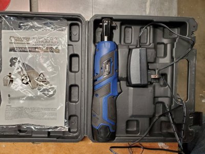
Today I picked up an electric 3/8" ratchet good to 22 ft-lbs from Princess Auto. ElectricRatchet.jpg
I tried it and it really does tighten up well and once loose since max speed is less than 4 revs per second it's easy to stop it bore the R8 collet drops out while I'm catching the TT holder.

But, it also tightens so well that I wasn't able to break it loose with my 1/2" torque wrench set to 22 ft-lbs because the spindle servo motor just can't handle that.

I don't currently have a WUT under the nut so I can't hold back the turning of the spindle. I think in the long run some sort of spindle lock is warranted. Underneath this plate I have access to the splined spindle shaft and I believe if I make a pivoting toothed lever I can use a solenoid to push it into place which will lock the spindle and then be able to easily tighten/loosen the draw bar.

As before I'll have two options (I have them now but the butterfly doesn't listen well). A quick press on the release or load button turns the nut a max of two times or until it stops turning. A hold down on the button causes continuous operation for up to 5 second or when button is released. This is to let the entire R8 assembly come out. (Software is the easy part).

The hardest part is going to be the reversing. The ratchet does that (being a ratchet) with a knob on the top. I just want to change the direction of the motor so I may have to figure out a way of locking the ratchet so forward or back create the same motion. However, the internal part of the electric ratchet sounds more like an impact wrench so it may not be the solution.

Works real nice right now for manual tool changes.
 

Attachments

  • MillSpindleAccess.jpg
    MillSpindleAccess.jpg
    72 KB · Views: 1
It feels like I'll be duplicating your setup. I'm just too short to keep dealing with my drawbar manually.
 
Here's my idea for a spindle lock. I think if the gap is big enough between the plate and the spindle teeth the pivot point doesn't need to be too far away. Mill out of 3/8" thick aluminum.
SpindleLock.webp
 
And throw a solenoid on the other end?
Yup. And an NC micro switch with the Spindle Enable signal in series with it. So when the switch opens as the bar moves away it prevents the mill from turning but also release the hold the spindle motor has on the spindle (AC servo with step/dir so it stays put normally). That allows whatever turns the draw bar but to rotate the spindle enough so it latches and then spindle drive is disabled.

I could rotate the spindle until the lock seats but the idea is to be able to use this manually without the CNC control if I need to.
 
OK. Spray glued the 1:1 print of the drawing onto cardboard. Gee I hate spray glue. Trimmed it to the lines and then started trimming away until it fit underneath. Once I pulled the cover I found I'd have to do some more trimming but for now I just raised it above the recess. I already had two holes in line with the spindle center line (approximately).

SpindleTestLock.jpg


Then laid it back onto the mill. Raised the quill back up and moved the cardboard back and forth to engage and disengage the lock. I think an eccentric pivot might be useful to line it up perfectly.

Here's a top view with the cover laid in place and the lock pivoted into engagement. Takes very little movement to pull it out and clear of the splines.

SpindleTestLock-1.jpg


You can see how the entire lock mechanism could be shifted to the right a millimeter or so but then the spindle could also be turned a bit. It's very close. I think a spacer under the flying end so it sits proud. Easier to attach spring and solenoid.

Anyway, just rambling out loud.
 
Bit the bullet this evening and ordered a 25:1 planetary reduction drive. With the DC motor I have on hand I theoretically should be able to apply the holding torque (25 NM) on a TT Holder in about 2 turns.

PlanetaryReduction.jpg

This should be reasonably easy because I've been there before. This photo shows a CAN bus controlled DC Servo coupled through the 3D printed holder to a 100:1 reduction drive and then a worm drive to move the lever up in less than 30 seconds. The key part here is that it moves in velocity mode but snugs up to the upper stop or the stowed stop using torque mode. Just enough to press hard but not break anything. The photo is of the simulator. Sorry I can't show the real end product; only the simulator.

BaseDriverSide.jpg

It's not that different from what I want to do. Turn for a distance X at full speed and a specific torque value. When it is no longer turning at torque Y then stop. That's for tightening. To loosen if it's a TT holder then set distance to 2 turns after the reduction drive and set torque to max. Decelerate to a stop at distance 2 turns. If it's an R8 tool then set distance to more like 16 or 18 turns.

In the case of the draw bar I have the up down motion to deal with. If it doesn't go all the way down then bring it back up, turn 1/12 of a turn and lower to line up with the flats on the draw bar. Or something to that effect.

No idea when this will arrive. Lots of projects on the go so no lack of anything to do.
 
One of the sites I spend time on occasionally has a thread for supporting the UHU DC Servo drives. A bit of background. Uli Uber (sp?) in Germany designed a DC servo drive driven by an 8 bit Atmel processor (around 2005) He also published the schematic and circuit board layout and a number of people around the world built some boards. I bought one from Manjeet in India. To make the boards work you had to buy the processor and crystal from Uli for the price of a beer or thereabouts. Here's mine.
Test_UHU.jpg


It worked well enough that a guy with the id Kreutz took the design and redid it to handle much higher voltage and current along with both a continuous and max current setting. Still used the same processor from Uli. Requries 15V and of course whever high voltage you might want for the motor. The encoder circuit was now also differential to combat noise. I had two of these set up on my mill for X and Y until discovered that the X motor had issues and kept loosing steps. Which is why it's nice to keep the DRO on the machine even if you go CNC. The one mistake I made was using the wrong polarity on the DB-9 for terminal communications. It's optically isolated too so it needs that USB connector for the PC side 5V.
HP_UHU_Modified.jpg


The next step in this project was done by Henrik Olsson in Sweden. He developed a little companion board with a PIC18 that had quadrature encoder support so that higher res encoders running at higher RPM could be used. He wrote his own code which he claimed was less sensitive to encoder noise because of the hardware QEI. Because of my X axis losing steps issue I bought a couple.

HO_HP_UHU.jpg


That cleaned up most of my problems but every once in a while the HP_UHU still had issues so eventually I moved to the Bergerda AC Servos since the cost of a replacement motor was the same as a 400W servo with drive and no power supply was needed. And because I was in the market for a 3 phase spindle motor and VFD I checked the price of that verses a 1.8kW AC Servo and the two motors with drives ended up being cheaper.

So why the story? Well Kreutz vanished for a while but recently returned to the UHU forum. And chatting with him about my issues with wanting a constant torque mode for my Draw Bar he found this thread on the forum.

Seems this fellow, Ray Livingston, has done the same thing that I wanted to do except he's using a 400 oz-in stepper, 55:1 planetary reduction, a Gecko stepper Drive with a relay to change motor current by adding in a resistor. Way back in 2012.

From the video it appears to work quite well. He's not posted anything since unfortunately. I've only ordered a 25:1 planetary reduction but then he's got the potential of 110 ft-lbs which is a tad high.
ie. 400 oz-in divided by 16 oz/lbs and 12"/ft is 2 ft-lbs static torque. With 55:1 that's a lot of static torque for a drawbar that doesn't need more than about 20 ft-lbs.

Finally to add one more thing to this story, Henrik Olsson is willing to help me update his code to a dsPIC that has hardware quadrature, PWM and CAN bus. A new module will be built that will replace the comparators used for detecting over current. With that, the ability to duplicate the german servo motor I used in that project I described in the previous posting will be possible.

Anyway. That's about it on this for now. Next step is to machine up a Size 23 mounting plate for the surplus PA motor in the first picture. Then do some testing to see if it's got the torque to do what I want while I wait for the reduction drive.

edit: The motor in the previous posting was French not German. https://sonceboz.com/en/
 

Attachments

Last edited:
Learned a lesson a few days ago.....bruised thumb and ego, broken butterfly wrench, bent drawbar nut, and socket thrown across the shop.....

Phone call during tooling change, left butterfly wrench on nut on mill to answer important call...started machine after call....butterfly wrenches aren't balanced trying to get up to 3000rpm....

Lesson learned, nothing seriously broken or no major injuries.

Now I will build a drawbar wrench with prevent that from happening again.
 
Here's a commercial version very similar to what I'm building.
 
So for now I've put the existing power draw bar aside while I wait for the planetary reduction and do some upgrades to the servo motor and drive.
Still need to be able to tighten and loosen the tools though. And without a spindle lock which is in the works I'm back to using the WUT.
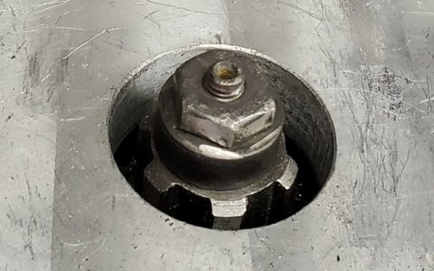
I enlarged it on the lathe to 16mm ID so the shoulder on the new draw bar nut would fit through. Visible in this photo. The actual drawbar hex head is a grade 8 bolt, annealed and drilled,tapped to thread onto the shaft. Then welded onto the shaft along with the larger round base.
UpdatedDrawbar-1.jpg

The original that came with the machine (square head now machined as hex) was so soft the impact wrench rounded it pretty quickly when it rammed on crooked. This shows what I wanted before I made it out of steel and welded.
DBAR-FIT-8.jpg

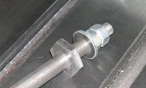
Now the rounded part was from 1" steel so too large for the 24mm wrench. Thank goodness for carbide inserts. The nut assembly after hardening was hard. But now the 24mm wrench fits over that and anchors the WUT to prevent it from turning while the 19mm box end turns the draw bar.
UpdatedDrawbar-2.jpg


Now that I can mill again, I can cut out the spindle lock and make the DC Motor mounting plate.
 
BTW, this is the sort of thing that was happening with the original draw bar and even now occasionally but with less force on the new one.
The pneumatic force pushing it down was fast enough and hard enough to not make the draw bar or socket turn but instead just jam on.
Humans are far more gentle and they will subconsciously wiggle things to get them to slide together.

DrawbarJammed.jpg
 
I find using the butterfly wrench that I don't need to lock the spindle to turn the draw bar, current on some holder still need to give it a tap to get the holders to let go.

I'll address it with a nut stop which will not allow the nut to rise and forces the holders down.

I am going to keep the auto/manual wrench simple to avoid failure points.
I also find that with the AC Servo Motor holding the current position that the spindle is sort of locked for the butterfly. But with wrenches the pulley spins in the V belt. I imagine once I have toothed belts it will be better. But the torque on a 2 HP motor is way lower than the 20 ft-lbs for an R8 Collet so it would still be easy to spin the motor. Hence the need for a spindle lock.

Look at the WUT article in HSM by Rick Sparber what he did

One option is capture the WUT onto the spindle and have a shoulder on the draw bar. So now when you turn it CCW the drawbar can't go up so pushes the collet downwards.

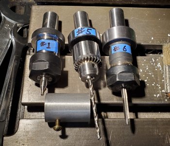
I find if I center drill, pilot drill, tap drill, clearance drill and finally tap that I've done 5 tool changes. And since my TT holder with the jacobs chuck is only good to 1/4" (should really order a 3/8") that the tool changes are more involved.
Tool #1 Center Drill
Tool #5 Jacobs chuck with pilot drill.
Tool #5 again for the other two drill bits although the clearance drill bit is often in a TT ER collet.
If the drill is too large then TT 0.75" R8 collet comes out and in goes the big ball bearing drill chuck.
Then out again for the 3/4" TT Holders and Tool #10 for the tap.

If I've done face milling on the part before I drill the holes then the 3/4" R8 TT Collet comes out for the R8 4 carbide cutter face mill.

Then the 3/4" R8 goes in again.

Now I'm really tired...
 
Look at the WUT article in HSM by Rick Sparber what he did
Drawbar with Integrated Spindle Lock

My round column mill drill clone has the WUT arrangement on it. It looks original. I've had it since 2012 and it was well used when I got it. I think the idea is WAY WAY older than Sparber's article.

I improved on mine by adding a centering locator button on the washer to reduce drawbar rattle.

I also added the centering button to both BPorts I had here. It was a little tricky to do because the thread on the drawbar of both mills is rolled not cut. I solved that problem by threading the washer and button and then drilling out the threads to the OD of the bar so they thread on at the bottom of the bar and then slide on to the top.

My draw bars don't rattle anymore.

Of course, the BPort and its clones have a spindle brake.

What does TT mean in your write up?

Should WUT and TT be added to the Acronym thread or are they so rarely used as to suggest not using them at all?
His original article was in Home Shop Machinist. The photo of mine is from 2007.

TT stands for "Tormach" Tool holder. The shank is 0.75" and the R8 0.75" collet is ground flat instead of rounded. The back end of the holder has a recess for the little bit of R8 collet that sticks out. As the collet is pulled up into the spindle it seats the back of the TT holder against the spindle.

This makes inserting a tool repeatable from a length perspective. So on each tool change you don't have to change the Z axis zero position. That's done once and the value entered into the tool table.

Now when I do a tool change for #1, the spot drill I use a feeler gauge or piece of paper to find the zero on the work piece. Since #1 doesn't have a length I set the machine Z zero to that. Then go ahead and spot drill the holes.

Next tool change is #5. I insert it and because there is a length in the table the machine Z zero had now been 'adjusted' for the longer drill bit so the g-code assumes Z is still set to the surface of the plate.
For example: (I've added comments to describe what is happening)
(Standard 3mm Drill )
N2 T5 M06 G43 (Change to Tool #5 by moving to Tool Change position and use Tool Z offset)
N3 S2000 M3 ( Turn on Spindle motor to 3000 RPM).
N4 G0 Z2.4409 ( Move Z to 2.4409" (62mm) above work to avoid and clamps.)
N5 X-1.1404 Y-0.6299 (Move X,Y to the first hole to drill)
N6 G83 X-1.1404 Y-0.6299 Z-0.4278 R0.0984 Q0.0965 F3.4 (Peck drill the hole)
N7 G80 (Cancel the canned drilling cycle)

The G83 parameters are explained here:
The G-Code was created automatically by AlibreCAM (AKA Mecsoft CAM)

When the power drawbar is working properly all I do when it pauses at the tool change position is tap the release button and catch the tool. Then hit enter on the PC keyboard. I think I posted a video showing that operation earlier spot drilling, drilling and tapping into a piece of oak.
 

Attachments

  • WUT-Rev1sm.webp
    WUT-Rev1sm.webp
    35.3 KB · Views: 3
  • ToolSet.jpg
    ToolSet.jpg
    610.6 KB · Views: 3
His original article was in Home Shop Machinist. The photo of mine is from 2007.

The article you linked to was dated Nov 2006. My mill drill is way older than that. Just trying to say that Sparber didn't invent that idea.

But it is a good idea.

Your work is awesome. I'm jealous. Although my equipment will never be CNC, it's very cool to follow what you are doing.
 
Back
Top