Update on this. I first tested a 45 degree and then 60 degree angle on a 17mm bolt head. Seemed to make it slip on more easily. So I turned a 60 degree angle on the 19mm draw bar bolt head. It does slip on more easily but still when off center the socket comes down so hard with the pneumatics that it hangs and I've seen the hardened impact socket actually leave a mark on the softer draw bar bolt.This is what I was thinking might work? As the inside flats of the socket out of alignment by 30 degrees, will tend to slide down the curve in the direction of one of the edges. The angle can't be too shallow or I suspect it would then still hang up on the surface.
Comments?
Not a dumb question at all.
The bushings in the impact wrench are designed to be oiled with the supplied air. As such spinning them without that oil might damage them. Then there's also the tangs inside the wrench that under light load may well click back and forth making noise.
A clutch such as this: DC Clutch might well work but the size is prohibitive without a total frame redesign.
Eliminating the socket would then also require a redesign of the end of the draw bar. At this point, aside from the redesign, there still needs to be a way to manually remove it if something fails with it tightly in place.
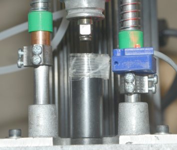
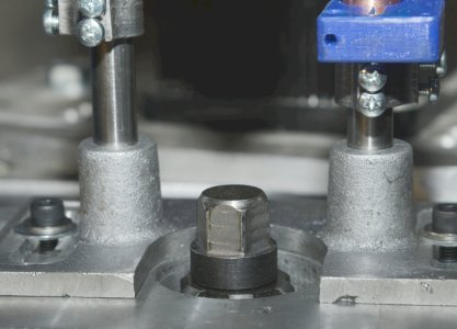
Again the big issue is for TTS tooling I want no more than 2 turns in the CCW and probably 3 seconds in the CW so the impact wrench can reach 15 to 25 ft-lbs of torque. The other postings with various rotary power draw bar subjects all use R8 tooling and spin CCW until the R8 drops out. Watch the videos closely of the manually engaged versions and if the socket doesn't go down all the way there's a slight twist of the handle to blip the air wrench just enough to move it slightly without excess pressure on the nut. And in one thread the need for the 12 point socket was emphasized. So when a human is involved the slight behavior changes are handled without thinking.
But I also want the ability to swap R8 tooling so mine is a dual operation draw bar. So far I haven't seen any other threads or you tube videos that deal with that.
If I were to start over I'd look at a 300 oz-in stepper motor and probably a 20:1 planetary drive. A few days ago the drives on Aliexpress were all in the $39 range. Yesterday they were all in the $70 range. In either case, a change to a fully electric version still runs up to $200 with drive etc. And some major redesign.
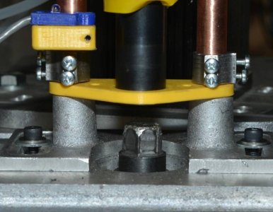
I've found one of the bigger issues is when the socket doesn't descend all the way and it starts to spin the magnet isn't lined up with the hall sensor so it defaults to timed turning which polishes or marks up the top of the draw bar even more. I think a switch to detect fully down before turning might be the solution. Then if it isn't down I can move it up, blip it to turn a tad, and try again. With a 12 point socket likely it will drop into place quite quickly and then a 2 turn spin to undo it leaves the R8 in place and the TTS drops out.
Thanks. Brings back memories of equipment I worked on in the early nineties. It was a 30 Ton Flywheel press with a clutch and absolute encoder. The clutch was engaged and as the flywheel rotated the micro-processor was interrupted on absolute locations. It would then load the next location for an event until the revolution was completed. Depending on what it was doing it would release the clutch or do another rev.I hear you. I'm just noodling the issues and asking myself what would I do.
Maybe that helps, maybe it doesn't. But at a minimum it provides other ways of looking at things. Starting over or switching to Gen II is always an option. "A wise man changes his mind often."
Here is a smaller clutch to consider. It's a riding lawn mower PTO clutch for the blade deck. Plenty strong enough and can be made much smaller than it is if you turf the pulley.
Thanks. Brings back memories of equipment I worked on in the early nineties. It was a 30 Ton Flywheel press with a clutch and absolute encoder. The clutch was engaged and as the flywheel rotated the micro-processor was interrupted on absolute locations. It would then load the next location for an event until the revolution was completed. Depending on what it was doing it would release the clutch or do another rev.
These events did thinks like engage air valves or tell stepper motors to move. All to move IC lead frames under the press for trimming, bending and forming the leads of the ICs.
The issue of cost has to be factored. A reduction drive and stepper/servo motor can, in addition to controlled speed and position can also control torque. Assuming the curve says the motor has 288oz-in of torque then that's 1.5 ft-lb. If I want between 12 and 20 ft-lbs then a 10:1 planetary gear box would create 15 ft-lbs. If I set the current to create 12 ft-lbs and turn it slowly as it tightens then I get predictable torque. If I set to 15 ft-lbs for unloading then I can turn it slowly at full torque for 1/2 a turn and then quickly for 1.5 turns. But then it might be nice to close the loop and have an encoder on the back of the motor too.
That would allow fractional turns if the first try didn't move the socket all the way down.
Like you said, different ways of looking at things. Since I've done this kind of computer controlled hard for many decades it's the way I tend to look at it.
My ELS still does awesome threading with 1PPR under the restriction that the spindle speed as to be solid. Even then it did track variations on the smaller Sherline Lathe. Not to say the larger PPR isn't better but at the time I designed the ELS an encoder pulleys and belts were more expensive than the entire ELS kit which included a micro-stepping driver for the Z axis.
I designed a CDI multi-point fuel injection ECU for Honda VTEC that were used in home built aircraft and hovercraft. We only used two sensors: one at TDC and one at 20 degrees (I think) BTDC. One one rev an engine just doesn't change speed that fast.
Firewall Forward Engine Control
That was all a long time ago now when we still had to use UV Eraseable EPROMs.
This was the precursor to what is now an Arduino. Monitor program in Mask ROM. Expansion bus with EEROM and 32K RAM added an RTOS I wrote and a Tiny PASCAL Interpreter written by the late Ian MacKay that could create tasks for the RTOS.
I still have all the old S100 boards and a couple of boxes along with my PERSCI 8" drive. An original 8" Turbo Pascal Disk etc. Probably about 10 years ago I tried to boot once of the machines and the disks no longer read. The graphics cards, including my wire wrapped video board are all worse than a Raspberry Pi or Beaglebone so the reality is I should really just put the stuff up on EBAY. Hard to let go and yet I know I won't do anything with it.I think what hurt the most was the s100 boards - especially all the a/d & d/a stuff. But then again, now you can get an add-on package for a tablet or laptop that will do all that better and faster for much less.
Pretty sure I still have a few old 8" drives too. But I knew even at the time that they would only be parts for other stuff. When you watch tape drives turn into way bigger 5.25 drives with 8" coming in the side door but never making it into the regular stuff because way bigger 3.5 stuff was arriving and then the first hard drives doubling every year and look where we are now! Omg! Bigger drives just empowered bloat ware.I still have all the old S100 boards and a couple of boxes along with my PERSCI 8" drive. An original 8" Turbo Pascal Disk etc. Probably about 10 years ago I tried to boot once of the machines and the disks no longer read. The graphics cards, including my wire wrapped video board are all worse than a Raspberry Pi or Beaglebone so the reality is I should really just put the stuff up on EBAY. Hard to let go and yet I know I won't do anything with it.
What I have on hand, like the dsPIC30F5011 based modules that I designed and built are way more powerful than an entire S100 mainframe. Funny eh? One of those to control my power draw bar. Here are 3 of them. The gold box xIM are the PIC based units. BIM has analogue, PWM, CAN bus, RS485, Relay drivers, and is set up for 0-36V input measurement along with thermister measurement. The B stands for Battery Interface Module and it started life as a BMS for large batteries. The other one is a GIM for Generator interface and controlled an ONAN diesel Genset with a small plug in board and that's what I'm using for the Power Drawbar. There is one more version not in the photo that has 6 more relay drivers and some I/O plus RS232 all on the RH connector instead of the A/D inputs.
Finally the white box (xMU) has another 16 bit processors (9S12) and has 5 CAN bus channels, 6 relay drivers, 6 dry contact to ground inputs, USB and an internal add on board with Real time clock and micro-SD for logging. The xMU one was designed in 2009 and initially a Rings Management Unit for the 2010 Winter Games in Vancouver. Now i use it for other projects to talk to other CAN devices like Motors, BMS, Solar Chargers.
Do you really think you can sell that stuff on ebay? I may have to open some of those drawers and start selling some of it. Better that then the kids and wife just trashing it when I leave this playground.
Bigger drives just empowered bloat ware.