• Scam Alert. Members are reminded to NOT send money to buy anything. Don't buy things remote and have it shipped - go get it yourself, pay in person, and take your equipment with you. Scammers have burned people on this forum. Urgency, secrecy, excuses, selling for friend, newish members, FUD, are RED FLAGS. A video conference call is not adequate assurance. Face to face interactions are required. Please report suspicions to the forum admins. Stay Safe - anyone can get scammed.

METAL LATHE SMOKE, RPM LOSS, NEW LATHE MOTOR?

Hi MM, Guys,

The Tach should be wired before the VFD and should be using shielded cable. The ferrite rings in the tach lead should help as will a capacitor of about 1000 pf wired across the tach. There should also be a mains filter either built into the VFD or in the mains supply directly before it. There should also be a mains earth terminal that should be used on the VFD and continued to the lathe metalwork.

VFD's are basically very electrically noisy things, its a function of how they work. In Europe it is mandated that things like VFD's, have mains filters built in as have many other electrical appliances.
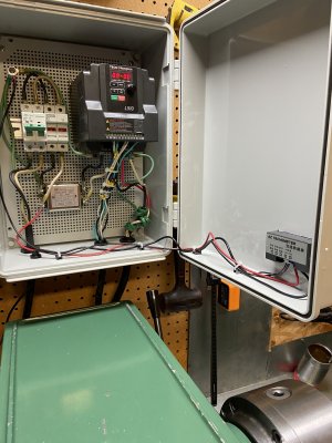
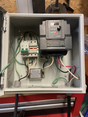
I'll add the ferrite rings after the vfd out to the motor, I'll try wrapping the tach cable as well , my computer is about 8ft away and has no issues, the tach cable did not come shielded but that's an easy fix. I did put a filter before the vfd, basically copying Clougs42's setup other than the ferrite rings which I had to order.

cheers and thanks
 
I'll add the ferrite rings after the vfd out to the motor, I'll try wrapping the tach cable as well , my computer is about 8ft away and has no issues, the tach cable did not come shielded but that's an easy fix. I did put a filter before the vfd, basically copying Clougs42's setup other than the ferrite rings which I had to order.

cheers and thanks
Hi MM,
I salvage my ferrite tubes, rings and cores from old computer cables and others. You can tell if a cable has a ferrite in it because it will have a lump at one or both ends.

Be careful adding ferrite rings in the VFD output cable it can cause problems, screened cable would be better.
 
I'll add the ferrite rings after the vfd out to the motor, I'll try wrapping the tach cable as well ,

I would NOT add ferrite to the VFD OUTPUT - only to the input.

You can buy reactors for the output but they are expensive and they will likely interfere with SLV mode. If you are concerned about output noise, you can use shielded cable.

More than likely, your interference is coming from the inputs, not the outputs. You can and should filter the inputs. Make sure. You tap into the power for your tac BEFORE the input filters. If need be, you can also use a lower power filter on the input to the tach.

If you know a sparky in your area, they can use an oscilloscope to look at your wiring and noise levels.

We previously discussed your input wiring and you indicated that you are getting your 120 input from half of your 220. This strikes me as rather odd. Very few 220V garage/shop services supply all 4 wires for such circuits. Usually, they omit the neutral because it isn't needed in a 220v circuit. However, if you want to split a 220V supply to get 110V, you need the neutral. Although it might work, you cannot and must not use the ground as a neutral. Doing so is a very serious safety risk.

Could you please confirm that your 220V supply has four wires in it?
 
I would NOT add ferrite to the VFD OUTPUT - only to the input.

You can buy reactors for the output but they are expensive and they will likely interfere with SLV mode. If you are concerned about output noise, you can use shielded cable.

More than likely, your interference is coming from the inputs, not the outputs. You can and should filter the inputs. Make sure. You tap into the power for your tac BEFORE the input filters. If need be, you can also use a lower power filter on the input to the tach.

If you know a sparky in your area, they can use an oscilloscope to look at your wiring and noise levels.

We previously discussed your input wiring and you indicated that you are getting your 120 input from half of your 220. This strikes me as rather odd. Very few 220V garage/shop services supply all 4 wires for such circuits. Usually, they omit the neutral because it isn't needed in a 220v circuit. However, if you want to split a 220V supply to get 110V, you need the neutral. Although it might work, you cannot and must not use the ground as a neutral. Doing so is a very serious safety risk.

Could you please confirm that your 220V supply has four wires in it?
-4 wire in, yes just went and made sure, I have a sub panel in my little shop and power is distributed from there and has incoming 4wire. I originally wired it just for my welder but now I share it with the mill/lathe via an extension cord (one cord)

-I did try the tack before the filter and after, made no difference until I turned the vfd off and spun the chuck up with a drill, I'll try shielding the tach cable first.
 
-4 wire in, yes just went and made sure, I have a sub panel in my little shop and power is distributed from there and has incoming 4wire. I originally wired it just for my welder but now I share it with the mill/lathe via an extension cord (one cord)

-I did try the tack before the filter and after, made no difference until I turned the vfd off and spun the chuck up with a drill, I'll try shielding the tach cable first.

OK. I was just making sure.

In any event, don't put a filter between the VFD and motor. Even if it worked, it would be bad practice and might have a, serious affect on the operation of the VFD.

If the Input filtering doesn't work, then we can probably assume the filter isn't good enough. Quite frankly, I didn't like Clough42's filter. Although it did work for him, it seemed like a rather haphazzard way to go about it. He didn't really optimize it. He just chose some components to throw at it and it worked. Good for him, but that approach isn't for me.

I'd like to see you try to run the tach off of a separate 110V extension cord to a different outlet.

Just curious, what rpm did your drill arrangement achieve?

Also, what carrier frequency is your VFD set to run at internally?
 
OK. I was just making sure.

In any event, don't put a filter between the VFD and motor. Even if it worked, it would be bad practice and might have a, serious affect on the operation of the VFD.

If the Input filtering doesn't work, then we can probably assume the filter isn't good enough. Quite frankly, I didn't like Clough42's filter. Although it did work for him, it seemed like a rather haphazzard way to go about it. He didn't really optimize it. He just chose some components to throw at it and it worked. Good for him, but that approach isn't for me.

I'd like to see you try to run the tach off of a separate 110V extension cord to a different outlet.

Just curious, what rpm did your drill arrangement achieve?

Also, what carrier frequency is your VFD set to run at internally?
I would have to check C42's video on the carrier freq, I just copied some of his settings, I'll try the tack on a separate circuit, today and see. 16 khz, just checked

I think I was able to get just over 115rpm on the drill but it was a real load on the drill, the tach stabilized which was encouraging.
 
I would have to check C42's video on the carrier freq, I just copied some of his settings, I'll try the tack on a separate circuit, today and see. 16 khz, just checked

I think I was able to get just over 115rpm on the drill but it was a real load on the drill, the tach stabilized which was encouraging.
wrapping the sensor wire with tinfoil made no difference as did a different circuit, did the drill test with the vfd on but the motor not running and it worked fine 225 rpm on the drill, the second I start the motor the problem shows up.
 
wrapping the sensor wire with tinfoil made no difference as did a different circuit, did the drill test with the vfd on but the motor not running and it worked fine 225 rpm on the drill, the second I start the motor the problem shows up.

Sure sounds like supply voltage noise to me. But I find it odd that a separate power source didn't help. Usually it does. That input noise must be spreading throughout your shop on all the wiring. That's not good. Lots of other problems are possible that you don't even know about yet.
 
Sure sounds like supply voltage noise to me. But I find it odd that a separate power source didn't help. Usually it does. That input noise must be spreading throughout your shop on all the wiring. That's not good. Lots of other problems are possible that you don't even know about yet.
interesting, my computer is less than 8ft away and no issues more like 6ft, like I mentioned, it only does it if the motor is actually turning the lathe, at idol it's fine.

I turned the freq down to 1 and worked my way up back to 16, it's stable while running at the lower limits then starts to get weird say after 4.
 
Last edited:
interesting, my computer is less than 8ft away and no issues more like 6ft, like I mentioned, it only does it if the motor is actually turning the lathe, at idol it's fine.

I turned the freq down to 1 and worked my way up back to 16, it's stable while running at the lower limits then starts to get weird say after 4.

Ya, your computer has a beefy robust power supply. You could make or buy a good power supply for your tach too, but it wouldn't really solve the problem.

The output frequency influence is interesting. I don't know off hand why that is.

In any event, I'm much more interested in your carrier frequency than I am in the motor drive frequency.
 
Ya, your computer has a beefy robust power supply. You could make or buy a good power supply for your tach too, but it wouldn't really solve the problem.

The output frequency influence is interesting. I don't know off hand why that is.

In any event, I'm much more interested in your carrier frequency than I am in the motor drive frequency.
yes carrier frequency was set at 16 then I tested it at 1 and worked my way up, no issues at 1-4 ish, if I am explaining it correct, motor drive is set to 80hz up from the 60hz line in.
 
yes carrier frequency was set at 16 then I tested it at 1 and worked my way up, no issues at 1-4 ish, if I am explaining it correct, motor drive is set to 80hz up from the 60hz line in.

Ah, I see. I thought you might be trying to run your motor at 1 to 4 Hz.

OK, so you mean it works when the carrier frequency is set between 1khz to 4khz.

That is condemning noise on the input lines feeding back from the carrier frequency.

What isn't obvious is that the tach has an internal frequency that it uses as a start and stop count pulses during its speed measurements. That frequency is probably what is sensitive to the input power noise.
 
Ah, I see. I thought you might be trying to run your motor at 1 to 4 Hz.

OK, so you mean it works when the carrier frequency is set between 1khz to 4khz.
Q
That is condemning noise on the input lines feeding back from the carrier frequency.

What isn't obvious is that the tach has an internal frequency that it uses as a start and stop count pulses during its speed measurements. That frequency is probably what is sensitive to the input power noise.
yup 1-4ish is all before it gets weird, even at almost full speed the tach stays stable at this low frequency, annoying sound but it does work.
 
@MooseMeat - did you see the questions above?
-no it's 110-240........

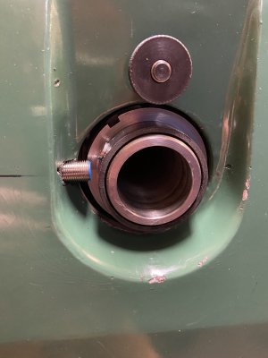
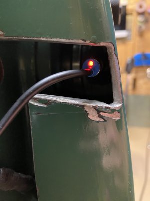
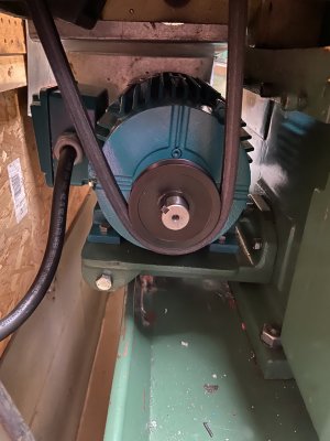
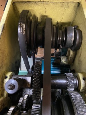
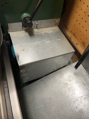
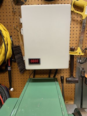
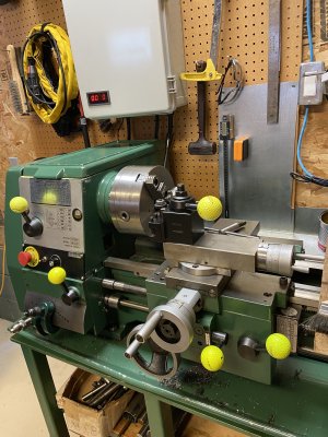
good news, problem solved, porn below, had to make a new cover the motor was longer than the original, new pulley, I have the original stepped pulley, and bored out the for the new shaft diameter 7/8 and just have to get the key relief cut in so I can use the original one and the tach works just fine now, you get one guess....😉
 

Attachments

  • IMG_6884.JPG
    IMG_6884.JPG
    1.7 MB · Views: 16
  • IMG_6883.JPG
    IMG_6883.JPG
    1.6 MB · Views: 12
  • IMG_6882.JPG
    IMG_6882.JPG
    1.9 MB · Views: 12
  • IMG_6881.JPG
    IMG_6881.JPG
    2 MB · Views: 10
  • IMG_6880.JPG
    IMG_6880.JPG
    2.2 MB · Views: 12
  • IMG_6879.JPG
    IMG_6879.JPG
    1.8 MB · Views: 16
  • IMG_6878.JPG
    IMG_6878.JPG
    1.8 MB · Views: 19
  • IMG_6844.JPG
    IMG_6844.JPG
    1.8 MB · Views: 18
  • IMG_6885.JPG
    IMG_6885.JPG
    2 MB · Views: 14
Back
Top