• Scam Alert. Members are reminded to NOT send money to buy anything. Don't buy things remote and have it shipped - go get it yourself, pay in person, and take your equipment with you. Scammers have burned people on this forum. Urgency, secrecy, excuses, selling for friend, newish members, FUD, are RED FLAGS. A video conference call is not adequate assurance. Face to face interactions are required. Please report suspicions to the forum admins. Stay Safe - anyone can get scammed.

METAL LATHE SMOKE, RPM LOSS, NEW LATHE MOTOR?

There is a safety reason that an ESTOP switch is Normally Closed. If the ESTOP event makes 'things' stop moving then a broken wire to the ESTOP switch would do the same thing.

Just imagine that you have something caught or is spinning dangerously. You duck down and hit the ESTOP and nothing happens because the wire to it vibrated loose a week ago because the ESTOP is Normally Open as is the broke wire. Impossible to close the circuit.
So would it have been wired to a contactor then?
 
There is a safety reason that an ESTOP switch is Normally Closed. If the ESTOP event makes 'things' stop moving then a broken wire to the ESTOP switch would do the same thing.

I get your point John. But a short would do the same thing to a normally closed switch. I suppose one could argue that open circuits are more common than shorts, but shorts do happen.

There is a way to protect both with pull-up and pull-down circuits. But maybe that's too complicated for an e-stop button.
 
So would it have been wired to a contactor then?
Essentially the concept behind the ESTOP is it shuts off all things hazardous to humans. In the past European rules meant that the PC would also be shut off. ie. the ESTOP shut down all AC so a contactor was held on by the not-pressed ESTOP.

It's true the ESTOP wiring could also short circuit although that then matters if it completes the contactor control signal to ground. Anywhere the wire could short to ground would then circumvent the ESTOP operation.

But if the ESTOP NC circuit connects the +24V (for example) signal to the contactor a short circuit to ground would open the contactor since it takes away the drive to the contactor just like when the NC switch opens.

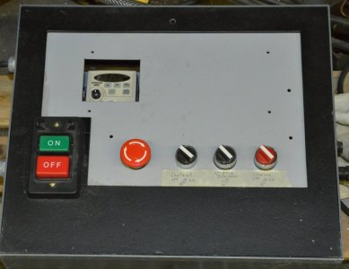
Attached is the wiring for my mill. At first glance it's pretty complicated and way more than what is required for a lathe.

The key 4 pole relay is called the KM relay. It's after the master switch and routes the 220VAC to the various motors and a step down transformer. The power to that relay coil is run through two NC contacts on the Spindle motor switch and Coolant pump switch along with the ESTOP switches and the ESTOP relay.

If either the spindle or coolant is switched on (or the ESTOP is active) before power is applied the KM contactor will not close so no accidental start up of the spindle when the master switch is turned on.
With the ESTOP off, spindle and pump off, the KM relay switches on and power to the KM relay is routed around the two spindle and pump safety switches.

Now an ESTOP switch opening will shut off the KM relay and AC power to the motors. Also if the PC Charge Pump signal vanishes (as in PC isn't power up or software has gone bye-bye) then the signal driving the ESTOP_RLY vanishes and again master power is shut down.

Hope that all makes sense.
 

Attachments

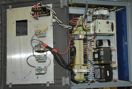
Here's the lathe power supply drawing. I see I put a comment about it being untested. Don't remember why I wrote that. It's quite crowded inside the box.

Notice how the System Relay connects to the VFD DI3 input which is connected to VFD COMMON when the system relay is switched OFF. Not sure it matters since AC is also removed from the VFD at the same time.
 

Attachments

  • LathePowerSupply.pdf
    LathePowerSupply.pdf
    119 KB · Views: 5
  • ControlBox.jpg
    ControlBox.jpg
    101.5 KB · Views: 1
  • ControlBoxInside.jpg
    ControlBoxInside.jpg
    154.4 KB · Views: 2
Here's the lathe power supply drawing. I see I put a comment about it being untested. Don't remember why I wrote that. It's quite crowded inside the box.

Notice how the System Relay connects to the VFD DI3 input which is connected to VFD COMMON when the system relay is switched OFF. Not sure it matters since AC is also removed from the VFD at the same time.
Looks to be very complicated to a laymen for a very simple issue, we seem to be entering into the realm of the "dark arts" of electrical.

cheers...
 
Looks to be very complicated to a laymen for a very simple issue, we seem to be entering into the realm of the "dark arts" of electrical.

cheers...
Ha ha. Yes. As I said it appears very complicated but there are several things going on here. There's the 12V power supply for my ELS. Also that older version of the ELS has the micro-stepper motor driver as part of the product because back then a micro-stepper driver ran around $100 and the parts to build one were about $25 so it made sense to build it into the product.

And since there's the micro-stepper driver there's also the power supply for the stepper motor. Finally since the VFD is a 220VAC unit and I wanted 120V for lamps and the coolant pump there's also a transformer to make 120VAC from the 220VAC.

That means all the other switching needs to be there for that stuff.

But at the simple level, a contactor to switch the 220VAC off when ESTOP is hit. Ideally low voltage through the ESTOP switch so a 12V powered contactor. The ESTOP NC contact controls the high side of the contactor and one of the contacts controls the stop switch to the VFD. Although not really needed since power is gone.
 
@MooseMeat and other contributors: My somewhat senile post 128 is a result of replying on my phone - which i am a novice using - thinking that I was seeing the end of the thread, not realizing that the project was nearly complete.... I thought it was in the very beginning stages. oops!

...Nice work! It looks great!

KMS seems to be a company that is trying to sprint toward bankruptcy. Their prices tend toward unreasonable, I find the staff unhelpful, and some cases downright rude. It motivates me to buy online, as the experience is so poor. I really do try to keep brick and mortar alive, but You can't help stupid.
 
Looks to be very complicated to a laymen for a very simple issue, we seem to be entering into the realm of the "dark arts" of electrical.

My lathe setup (which is not done yet) will be KISS - like my mill.

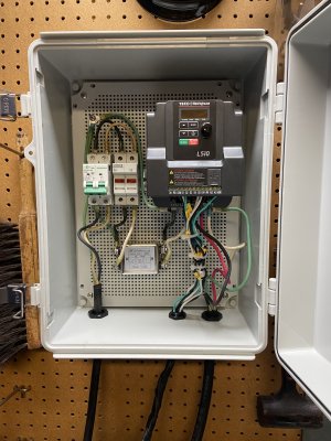
There is input filtering but no mains switch. It is powered up when plugged in.

The EStop is NO and uses the rapid stop functionality of the TECO VFD.

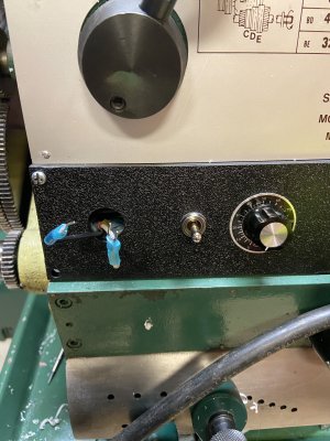
The fwrd/rev stop uses a Single Pull Double Throw switch on the mill and the lathe carriage lever switch on the lathe.

An inching function uses a momentary contact button switch.

There are no relays or contactors.

A simple variable resistor on the front panel controls frequency.

I suppose that input power could be switched but I didn't bother. Both my mill and lathe arrived here with power being switched on/off by plugging it in or by pulling the plug. That is probably how they will stay because two cables on the floor is more than enough.

I don't use the 220 to make 110. One of the floor cables is just plugged into 110 to supply 110 as needed for things like DROs, lights, and tool post grinders.
 
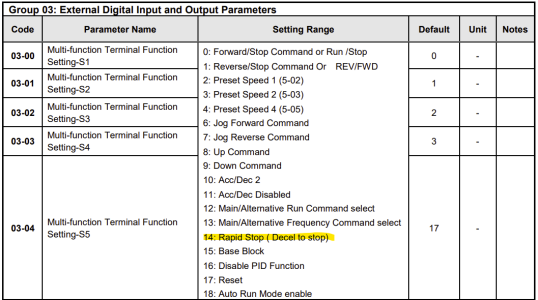
Yes. Use S5 with it's function set to 14 (Rapid Stop).


View attachment 70634
Works great, so when you activate the stop command putting the rev/fwd switch in the centre position reactivates the normal run function. The switch will be here Monday so the wires are loose for testing, put everything in a better box too.

I am amazed how quiet the motor is after using Clough42's settings, purrs like a newborn kitten. I am definitely missing something here on connecting accessories, two terminals are left, S3/S4 how does the vfd know if I add a jog function, maybe, ok well I do know I'm not understanding something correctly on how to assign what wire to what and tell the vfd to do something.

😉 thank you...

can't not post pics, I'd get a beating by some members here if I didn't
 

Attachments

  • IMG_6857.JPG
    IMG_6857.JPG
    1.8 MB · Views: 11
  • IMG_6856.JPG
    IMG_6856.JPG
    2.2 MB · Views: 12
Last edited:
I am amazed how quiet the motor is after using Clough42's settings, purrs like a newborn kitten.

This is something I keep harping on. It has to be seen, heard, and felt to believe it.

Are you set to SLV mode yet? If not, you should. Another level up in smoothness yet again.

I am definitely missing something here on connecting accessories, two terminals are left, S3/S4 how does the vfd know if I add a jog function, maybe, ok well I do know I'm not understanding something correctly on how to assign what wire to what and tell the vfd to do something.

It works the exact same way as how you wired and programmed S5. You wire each one up as needed, and then you program the function you want for each one you wired. First you need the circuitry, and then you need to program the VFD so it knows how to use that circuitry.

You might be getting confused by the fact that there are 5 functional switches S1 to S5. They are each individually programmable to do any of the functions in the function option list. You chose S5 to be the fast brake. But you could have chosen any of the others instead.
 
This is something I keep harping on. It has to be seen, heard, and felt to believe it.

Are you set to SLV mode yet? If not, you should. Another level up in smoothness yet again.


It works the exact same way as how you wired and programmed S5. You wire each one up as needed, and then you program the function you want for each one you wired. First you need the circuitry, and then you need to program the VFD so it knows how to use that circuitry.

You might be getting confused by the fact that there are 5 functional switches S1 to S5. They are each individually programmable to do any of the functions in the function option list. You chose S5 to be the fast brake. But you could have chosen any of the others instead.
I kinda get it, sort of but not really
so if I were to add a "jog" switch and I have two open terminals, say S3/S4, would the jog switch be a three wire momentary on/off wired to the S3 and the common, but how would it jog in reverse and then forward if the main switch was in the forward position. Do I have to use both S3/S4 terminals for forward and reverse jog and program them along with tying into the common?

I think I'm a complete dolt when it comes to electrical, in skool 😉 my teachers cast me aside because I asked how the machine works, they couldn't explain it, only the outcome of the function of the machine, which was not good enough for me to learn.

So what is the "common" is it the "anchor" then in combination with S3 it jogs forward if programmed to go forward, then the S4 is programmed for reverse, kinda like the fwd/rev switch?

SLV mode, yes I just copied Clough42's settings, smooooooth I will say.

Not trying to be a PITA, I do appreciate all the help here.
 
Hi MM,

It will jog in whatever direction you have chosen/selected !
You only need one terminal programed for jog.
 
Last edited:
I think I'm a complete dolt when it comes to electrical, in skool 😉 my teachers cast me aside because I asked how the machine works, they couldn't explain it, only the outcome of the function of the machine, which was not good enough for me to learn.

I taught myself basic electrical/electronics when I was a boy. That gave me a big leg up in class later in life. It also hurt me because my methods were non-orthodox. It was the same with math. I often got the right answer using the wrong method and got zero marks. I remained pissed off about it for life. In industry I was pissed off that mechanical industrial civil and materials engineers couldn't do basic electronics. Not even really simple stuff. Yet they had all taken basic electrical. WTF. I think schools make it all too difficult and it's often taught by rote and not by understanding. It should be simple but they make it hard by insisting on methodologies and subject matter that will never be relevant to the students future life. So I developed our own internal course. Even many electrical engineers liked it. I ended up teaching it at university too.

Basically, you are not a dolt. Your teachers were.

So what is the "common" is it the "anchor" then in combination with S3 it jogs forward if programmed to go forward, then the S4 is programmed for reverse, kinda like the fwd/rev switch?

A single binary input cannot be used to do more than two things. It's one or the other. A mechanical bump switch with no smarts is used to bump forward or not bump forward. It can't do bump forward, not bump forward, or bump in reverse. Neither can a VFD. It would need to be a variable signal to do that.

In simple terms, if you want bump forward, don't bump, and bump in reverse, (3 different functions) you need to use 2 inputs. One for bump forward and one for bump in reverse.

If you only have one function switch input available, then you have to choose one.

There is a workaround though. Bump switches are momentary. Direction switches are latching. You could use a direction switch that has a momentary contact before it latches to accomplish the same thing.

My lathe only has bump forward. And even so I rarely use it. I haven't made my mind up yet on how I will impliment bump with my VFD, but most likely it will only be bump forward because I want to use all the same controls.

 
I taught myself basic electrical/electronics when I was a boy. That gave me a big leg up in class later in life. It also hurt me because my methods were non-orthodox. It was the same with math. I often got the right answer using the wrong method and got zero marks. I remained pissed off about it for life. In industry I was pissed off that mechanical industrial civil and materials engineers couldn't do basic electronics. Not even really simple stuff. Yet they had all taken basic electrical. WTF. I think schools make it all too difficult and it's often taught by rote and not by understanding. It should be simple but they make it hard by insisting on methodologies and subject matter that will never be relevant to the students future life. So I developed our own internal course. Even many electrical engineers liked it. I ended up teaching it at university too.

Basically, you are not a dolt. Your teachers were.


A single binary input cannot be used to do more than two things. It's one or the other. A mechanical bump switch with no smarts is used to bump forward or not bump forward. It can't do bump forward, not bump forward, or bump in reverse. Neither can a VFD. It would need to be a variable signal to do that.

In simple terms, if you want bump forward, don't bump, and bump in reverse, (3 different functions) you need to use 2 inputs. One for bump forward and one for bump in reverse.

If you only have one function switch input available, then you have to choose one.

There is a workaround though. Bump switches are momentary. Direction switches are latching. You could use a direction switch that has a momentary contact before it latches to accomplish the same thing.

My lathe only has bump forward. And even so I rarely use it. I haven't made my mind up yet on how I will impliment bump with my VFD, but most likely it will only be bump forward because I want to use all the same controls.
"In simple terms, if you want bump forward, don't bump, and bump in reverse, (3 different functions) you need to use 2 inputs. One for bump forward and one for bump in reverse."

So the remaining two open terminals, in this case S3/S4, on a there wire momentary on/off with a resting centre position the S3 could be set to reverse and the S4 set to forward and the centre wire to the common? Each of the functions, reverse is a functioning forward is a function shared by a common for the signal to left or right to take up the last open terminals; as we set S5 has been set to rapid stop shared with the common for a two wire connection.
 

Attachments

  • image-Sep-15-2025-08-14-06-7325-PM.png
    image-Sep-15-2025-08-14-06-7325-PM.png
    141 KB · Views: 0
So the remaining two open terminals, in this case S3/S4, on a there wire momentary on/off with a resting centre position the S3 could be set to reverse and the S4 set to forward and the centre wire to the common? Each of the functions, reverse is a functioning forward is a function shared by a common for the signal to left or right to take up the last open terminals; as we set S5 has been set to rapid stop shared with the common for a two wire connection.

Yes. You have the way of it.
 
HAPPY TIMES AHEAD

Pics to follow, estops arrived as with the pulley, all wired up, e stop/rapid stop although not a true e stop at least I have a big red button to push now. I put the new pulley on and the old belt, but I definitely need a longer belt the old one is way too tight, which brings me to a question, so I spun everything up, I have the vfd set from the top end of 60 to 100 htz for testing, I did see the motor slowing down at 100htz and feel it's because of the heavy load on the belt tension, I need your thoughts on this fellas.

Machine runs uber quiet and smooth, different story when I engage the gears for feed, sounds normal and that "geary" sound is definitely there, did I invent a new word? I would love to share a video here but not sure if I can upload one or have to link it through a third party, The original pulleys was a stepped pulley but I figure because of the vfd a single will be just fine as I can use the back gears and the other pulley steps.

So is my high pulley tension causing issues, I'm thinking so, but this was just a test run for function.

cheers, thanks all..
 
Back
Top