• Scam Alert. Members are reminded to NOT send money to buy anything. Don't buy things remote and have it shipped - go get it yourself, pay in person, and take your equipment with you. Scammers have burned people on this forum. Urgency, secrecy, excuses, selling for friend, newish members, FUD, are RED FLAGS. A video conference call is not adequate assurance. Face to face interactions are required. Please report suspicions to the forum admins. Stay Safe - anyone can get scammed.

METAL LATHE SMOKE, RPM LOSS, NEW LATHE MOTOR?

All I see in your pictures is a loose magnet.
it's actually crazy glued to the plastic ring,
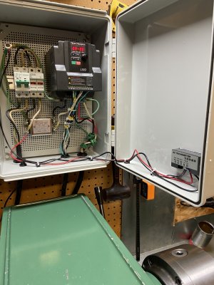
hint, there are two almost identical pictures but one is different, ignore the box the vfd is in, BIG HINT..... 😉

now it's my turn to torture you guys...........
 
1) As suggested earlier try powering the tach from a separate source.
2) Make sure the motor wiring and input power wiring are physically separated from the control wiring as much as possible, and especially the tach wiring.
3) If power and control wiring must cross, make them cross at 90 degrees, avoid at all costs running control and power wiring in parallel or in the same bundle or conduit.
4) Use a shielded cable for tach wire and ground the shield on one end only at the tach end.
5) Using AC-90 cable for power wiring would be a good idea.
6) Make sure you have an excellent earth ground to motor, VFD and panel.

In your picture the ac power wiring is running parallel to the tach signal wiring, that's not good.

Tach looks to be getting powered via chassis (earth) ground. That's really bad, if I'm seeing that correctly that needs to be fixed priority one.

Decent chance that tach can be powered from 240V, see if that's possible.

I would tyrap pad the VFD motor wiring to the RHS as much as possible.
I would tyrap pad the input wiring to the LHS and keep close to mounting plate.
Then only control wiring in the space between.
It almost looks like the white wire from filter is bundled with control wiring, even if it isn't, its too close and too parallel.
 
Last edited:
Pic 6844 doesn't show any wiring to the tach so that's inconclusive as a problem. Pic 6878 does show the tach wired and it looks okay.

My best guess,,,,,, you turned on the breaker.
 
Maybe get your wives to look, just saying..')

My wife wouldn't know a wire from a zip tie.

Cable vibrating on the housing? That isn't likely to be a problem on its own, but maybe it is moving the sensor?

I dunno @MooseMeat, you are there to see what isn't obvious to me in a photo.

Btw, I agree with everything @slow-poke suggests. They duplicate some of my suggestions but it's always good to hear different versions.

Anyways, glad you got this one figured out.
 
My wife wouldn't know a wire from a zip tie.

Cable vibrating on the housing? That isn't likely to be a problem on its own, but maybe it is moving the sensor?

I dunno @MooseMeat, you are there to see what isn't obvious to me in a photo.

Btw, I agree with everything @slow-poke suggests. They duplicate some of my suggestions but it's always good to hear different versions.

Anyways, glad you got this one figured out.
"My wife wouldn't know a wire from a zip tie."
kinda the same here 😉

OK I can't take it anymore,
there are two pictures of the vfd box, one is a plastic box with a grid in it the older other one is a metal box, that's just because I like the plastic box better with the screw grid, bottom right corner below the vfd in the newer box with the grid in it. SEE THEM DAM GREEN RINGS? 😉 the ferrites killed the problem.
 

Attachments

  • img_6878-jpg.71086.jpg
    img_6878-jpg.71086.jpg
    1.8 MB · Views: 19
wrapping the sensor wire with tinfoil made no difference as did a different circuit, did the drill test with the vfd on but the motor not running and it worked fine 225 rpm on the drill, the second I start the motor the problem shows up.
HI MM,

Did you make sure that the tinfoil shielding was earthed, either to the machine frame or whatever you are using for an earth.

One thing that I would not be happy about is using half the 220 volt supply.
 
SEE THEM DAM GREEN RINGS? 😉 the ferrites killed the problem.

Hmmmm. First he tells us not to look at the VFD system. Then he tells us to look at the ferrite rings in the VFD system...... Your wife must be a Saint!


Those ferrite rings might have very well killed the problem. But it looks like they are on the output to the motor. That is NOT a good idea. If the motor outputs are creating a problem, you should not try to reduce the problem. Instead you should try to isolate the problem noise so it can't affect anything else. The reason for this is that the VFD needs to see the full signal to the motor - not one that is filtered. Otherwise, it can't accurately measure what the motor is doing.

You can accomplish the same result by shielding the output cable. That doesn't stop the noise from happening. It just stops other devices from seeing it. Tin foil will not suffice.

Also, I would run your tach wires as far away from the motor output cables as you can get them. They look very close (too close) the way they are there.

I used braided shielded cable to my motor. That's probably overkill, but like your system probably has, mine had scary levels of noise on the outputs. I didn't want to risk seeing any of that noise reach any other devices in the area.

The braid mesh and the shield are both tied to ground at the VFD Ground terminal nearest the output. They are not connected to the motor and just float at that end. However, the motor is grounded with a separate ground wire inside the cable shielding.
 
Hmmmm. First he tells us not to look at the VFD system. Then he tells us to look at the ferrite rings in the VFD system...... Your wife must be a Saint!


Those ferrite rings might have very well killed the problem. But it looks like they are on the output to the motor. That is NOT a good idea. If the motor outputs are creating a problem, you should not try to reduce the problem. Instead you should try to isolate the problem noise so it can't affect anything else. The reason for this is that the VFD needs to see the full signal to the motor - not one that is filtered. Otherwise, it can't accurately measure what the motor is doing.

You can accomplish the same result by shielding the output cable. That doesn't stop the noise from happening. It just stops other devices from seeing it. Tin foil will not suffice.

Also, I would run your tach wires as far away from the motor output cables as you can get them. They look very close (too close) the way they are there.

I used braided shielded cable to my motor. That's probably overkill, but like your system probably has, mine had scary levels of noise on the outputs. I didn't want to risk seeing any of that noise reach any other devices in the area.

The braid mesh and the shield are both tied to ground at the VFD Ground terminal nearest the output. They are not connected to the motor and just float at that end. However, the motor is grounded with a separate ground wire inside the cable shielding.
When I tried the tack on a different circuit I moved the wires as far away as they would reach and same problem occurred, I can shield the output cable but will have to get some proper shielding.

A point to note, when researching the issue I came across this very issue with vfd's and the use of ferrites as an affordable solution if the cable shielding still won't work...... I'll try some shielding and remove the rings for a test and report back.

link on the use of ferrites.

 
This may be helpful,
cheers...


Ferrite rings can help reduce electromagnetic interference (EMI) in the output cables of a Variable Frequency Drive (VFD), but they do not directly control the motor itself. Instead, they are used to suppress high-frequency noise that can affect the performance of the motor and other connected devices. kebamerica.com Physics Forums

Ferrite Rings and VFD Motors​

Ferrite rings can be beneficial for motors connected to Variable Frequency Drives (VFDs). They help reduce electromagnetic interference (EMI), which can affect the performance of the motor and the VFD.

How Ferrite Rings Work​

  • Noise Reduction: Ferrite rings suppress high-frequency noise generated by the VFD. This noise can interfere with the motor's operation, leading to erratic behavior.
  • Common Mode Choking: When installed on the output cables of a VFD, ferrite rings act as common mode chokes. They help filter out unwanted signals that can cause issues in the motor's performance.

Installation Considerations​

  • Placement: Ferrite rings should be placed on the output cables of the VFD, ideally with the cable looped through the ring. This maximizes their effectiveness in reducing EMI.
  • Sizing: It's important to choose the right size and type of ferrite ring based on the frequency of the noise generated by the VFD. Higher frequencies may require specific ferrite materials.

Benefits of Using Ferrite Rings​

  • Cost-Effective: Ferrite rings are a low-cost solution compared to more complex filtering systems.
  • Simplicity: They are easy to install and do not require extensive modifications to existing systems.
In summary, ferrite rings can effectively mitigate EMI issues in motors controlled by VFDs, enhancing their reliability and performance.
 
The harm side of the equation;

Ferrite rings are generally used to reduce electromagnetic interference (EMI) in variable frequency drive (VFD) applications and should not harm the motor if used correctly. However, improper installation or using the wrong type of ferrite could potentially lead to issues, so it's important to follow manufacturer guidelines. kebamerica.com hobby-machinist.com

Impact of Ferrite Rings on VFD Motors​

Function of Ferrite Rings​

Ferrite rings are used to reduce electromagnetic interference (EMI) in variable frequency drive (VFD) applications. They help suppress high-frequency noise and minimize leakage currents, which can improve the performance of the motor and connected electronics.

Potential Risks​

While ferrite rings can be beneficial, improper use may lead to issues:

  • Common Mode Choking: If ferrite rings are not correctly placed, they can choke the capacitive return current, potentially causing erratic motor behavior or overheating.
  • Saturation: Using ferrite rings that are too small or not rated for the application can lead to saturation, which diminishes their effectiveness and may result in increased EMI.

Best Practices​

To avoid harming the motor:

  • Correct Placement: Ensure ferrite rings are installed on the output cables of the VFD, with the cable looped through the ring to maximize their effectiveness.
  • Manufacturer Recommendations: Follow the manufacturer's guidelines for ferrite ring specifications and installation to ensure compatibility with the motor and VFD.
  • Monitor Performance: Regularly check the motor's performance and temperature to identify any potential issues early.
By adhering to these practices, ferrite rings can enhance the operation of VFD motors without causing harm.
 
Each to his own @MooseMeat.

I don't really care how much you find in on-line advice sources. I spoke to the engineers at Teco back when I discovered all the noise on mine. They STRONGLY recommended against it. That's not tech support, that's their R&D guys. These guys know more than you will ever find on line.

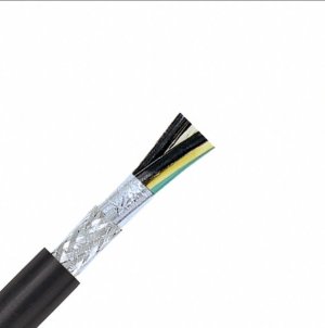
I also don't recommend installing cable shielding. I recommend shielded cable instead. The one I got was specifically rated for VFDs. It is 12G double shielded (foil wrapped and then mesh shielded). I originally sourced it at Digikey but they could not supply 12G, so I contacted the manufacturer and then bought 12G from the manufacturer through a local electrical supply outfit using the part number they gave me. It looks like this:

Screenshot_20251006_165550_Chrome.jpg

It was not cheap. And yes, it was also overkill. But the noise on my VFD Outputs was scary. I didn't want to risk interference with other electronics in my shop. I posted about the unusual noise on this forum a million years ago. Your system is apparently similar for reasons I don't understand. That's really too bad. It isn't supposed to be like that.

You cannot install shielding that will work as well as cable with shielding built in. Shielded cable must be run directly from the motor to the VFD. There will be no unshielded wires inside your cabinet except where they attach to the VFD itself.

If you want to understand the complexity of filtering VFD output, look into buying a VFD reactor. These devices are designed to work properly with the VFD and motor. Each one costs as much as the VFD and you need three of them - one for each phase. Even so, Teco advised that you might have to disable SLV mode with reactors in the circuit. No thank you!

Basically SLV mode measures instantaneous voltage and current to calculate back emf, load, and motor position. Filters change the timing of those signals which affects the SLV functionality of the VFD.

Will it work with filters and without SLV? Yup, it will. Do I want it like that? Nope, no thank you. But it's your system and your decision not mine.
 
@MooseMeat - I found that old thread for you.

Thread 'VFD Output Filtering' https://canadianhobbymetalworkers.com/threads/vfd-output-filtering.5996/

Pay special attention to @jcdammeyer's comments about coil saturation. This is the kind of thing that makes watching Clough42 and your VFD Filtering website so shallow. Both forget that it only works at low power levels. As soon as you crank up the load the coils saturate and might as well not be there. A classic example of "it worked great on the bench......"

As I have already stated. I gave up on trying to filter the output. It was waaaay too expensive to do that properly. It was easier to accept the noise and simply shield it from reaching anything else. That's how I arrived at using top notch shielded cable instead.

I probably have enough left for you too. But I don't know how to get it to you during the strike.
 
Back
Top