• Scam Alert. Members are reminded to NOT send money to buy anything. Don't buy things remote and have it shipped - go get it yourself, pay in person, and take your equipment with you. Scammers have burned people on this forum. Urgency, secrecy, excuses, selling for friend, newish members, FUD, are RED FLAGS. A video conference call is not adequate assurance. Face to face interactions are required. Please report suspicions to the forum admins. Stay Safe - anyone can get scammed.

METAL LATHE SMOKE, RPM LOSS, NEW LATHE MOTOR?

Hi Guys,

I've spent some time reading through that link, most interesting.

Using the tramming gauge that I made I determined that the mill head nodded about 4 or 4.5 Thou.
Since correcting the nod on these mills is quite a major undertaking, there are four bolts that secure the column , they are also thread locked as well. I had to use a rattle gun to break them free after using a propane torch on the bolt heads.

Having now got all four bolts free and was able to move the column enough to clean the crap of the joining surfaces, I discovered that I could fit all four bolts back and tilt the column complete with the head enough to be able to fit a shim in between the bolts.

I had calculated that I would need a shim about 5 Thou thick. In fact I found that a two Thou shim got the head within 1/2 a Thou of true. Surprisingly the tram in the table direction barely changed. I did readjust it and rechecked the nod, that didn't change either.

Whilst I think on, I do have a 10" inch brake rotor that I have used to quickly check the tram.
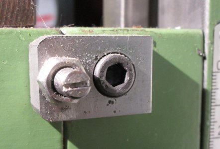
22-06-2025-003.jpg

This is the right hand side head stop.
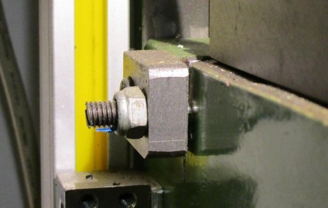
22-06-2025-001.jpg

And this is the left hand side head stop.
 
I had calculated that I would need a shim about 5 Thou thick. In fact I found that a two Thou shim got the head within 1/2 a Thou of true. Surprisingly the tram in the table direction barely changed. I did readjust it and rechecked the nod, that didn't change either.

The nod math is not as simple as it seems at first blush. The last time I did it, I said to myself that I should document it and save it.

I trust you are not shimming between the bolts but rather under each bolt. A central shim will put a lot of strain on the column casting and potentially add a lot of vibration and chatter.

One thing I neglected to say about a brake disk is that used disks have worn significantly with time and can easily exceed acceptable limits for this application. I recommend new discs. They can be had quite inexpensively. Some might need some polishing if they are too rough. If you can find a relatively smooth one, you are ahead of the game! I chose 12" simply because I could mount that on my lathe and polish it.
 
The nod math is not as simple as it seems at first blush. The last time I did it, I said to myself that I should document it and save it.

I trust you are not shimming between the bolts but rather under each bolt. A central shim will put a lot of strain on the column casting and potentially add a lot of vibration and chatter.

One thing I neglected to say about a brake disk is that used disks have worn significantly with time and can easily exceed acceptable limits for this application. I recommend new discs. They can be had quite inexpensively. Some might need some polishing if they are too rough. If you can find a relatively smooth one, you are ahead of the game! I chose 12" simply because I could mount that on my lathe and polish it.

I prolly would not have used a face mill, but it's not a fussy job. If it works, it works!

Good thinking to remove the metal from the bottom of the tool. My first time, I removed it from the top. That was a mistake.

What is your tool post size? They do make tall tool holders for AXA, BXA, and CXA. this basically increases your tool holders to the next size up. Mine being BXA, takes 5/8" tools. The tall BXA holders take 3/4" tools.


I'll readily confess that I don't think an indicator setup (either 1, 2, or 3) is nearly as useful as a tramming plate. A good plate makes the whole tramming process trivial.

I made a tramming fixture from a 12" OD brake disk. Brake discs are made to very exacting tolerances in order to prevent brake pedal throb and pulsing. A brake disc mounted ABOVE THE VISE, provides the following advantages:

1. You don't have to remove the vise to check or adjust tram.

2. You don't have to deal with T-slot incontinuities. You can just sweep smoothly and continuously.

3. But most importantly of all, a round disk provides a sweep range of 360 degrees extending the travel not just to both sides, but also behind and in front of the table making nod adjustments easy.

All you need is an inexpensive brake disk and 3 precision blocks - 2-4-6 blocks work great. You can buy them or make your own if you have a surface grinder (that's what I did). You can also make them on a mill but only if it's already trammed!

The blocks are placed on the table with two on one side of the vise front and back, and one in the middle on the other side. This allows the disk to be mounted above the vise.

Now you have a perfect surface that is perfectly parallel to your table on which to tram the mill head. Lots of members use two indicators and I made a fixture for 3 so I can tram without sweeping. But you can sweep if you want. One indicator is easy with the tramming plate. Two is easier, and 3 is easiest of all.

Here is a great thread from the past with lots of math, drawings, and ideas!

Thread 'Spindle square' https://canadianhobbymetalworkers.com/threads/spindle-square.4225/

Btw, @BaronJ - I don't recinme
It is a BXA tool post and the carbide holders are 1" that I cut down, I just ordered two more tool holders that accommodate 5/8 tool. I have so many carbides that came with the lathe I couldn't fathom not using them.

As for the tram duel gauge, I do have one, but it is in the .0005 range and I spent a few hrs messing with the nod, I'll have another proper go at it again tomorrow, I got frustrated so I switched to the .005 indicator and got really close, should I continue to chase the .0005? I was using tin foil as shims but I wasn't placing them under the back two bolts, tomorrow I will have a fresh perspective on it and shim under the rear bolts as the nod has to come down.
 
The nod math is not as simple as it seems at first blush. The last time I did it, I said to myself that I should document it and save it.
I intended to do just that, and never did.
I trust you are not shimming between the bolts but rather under each bolt. A central shim will put a lot of strain on the column casting and potentially add a lot of vibration and chatter.
Actually I put a piece of copy paper down between the bolts so that it hung on the top pair, down about halfway to the bottom, maybe 2" inches long and then clamped it back up. I expected the machine base to have a hollow in it, but it doesn't. Its just a large flat surface on both parts, about 5" inches square. It had been machined so I would have expected it to be true to the ways.
One thing I neglected to say about a brake disk is that used disks have worn significantly with time and can easily exceed acceptable limits for this application. I recommend new discs. They can be had quite inexpensively. Some might need some polishing if they are too rough. If you can find a relatively smooth one, you are ahead of the game! I chose 12" simply because I could mount that on my lathe and polish it.
I got my brake disc given to me as old stock !
Its 10" inches in diameter and is a single disc, no venting in it. I would have to measure its thickness but its about 5/8"ths or 3/4" inch thick.
 
I intended to do just that, and never did.

One of us should do that. Maybe next time. The nod on my big mill is at the head so it's not the same as an RF series mill. I never did tram my RF style mill-drill so there is that.

It had been machined so I would have expected it to be true to the ways.

I would fully expect that to be not true. The head is heavy and everything is rubber......

If I did do an RF, I would use big shim washers at the bolts, and I might mix some thin epoxy and put release agent on both surfaces to make a large wedge shaped shim. But maybe the epoxy is overkill.

I got my brake disc given to me as old stock !
Its 10" inches in diameter and is a single disc, no venting in it. I would have to measure its thickness but its about 5/8"ths or 3/4" inch thick.

Perfect!
 
All kidding aside here, I play'ed with the mill tram today and is this an accurate measurement, I ask not in jest because these machines are not the kindest to shim and re tighten the bolt 300 times, each cinch of the wrench can move the measurements.
 

Attachments

  • IMG_6918.JPG
    IMG_6918.JPG
    1.9 MB · Views: 6
  • IMG_6917.JPG
    IMG_6917.JPG
    1.9 MB · Views: 6
Can't really say @MooseMeat. I would need to see the changes as you sweep around the full 360. Where did you zero? How did you zero? What goes up and what goes down as you sweep.
 
Can't really say @MooseMeat. I would need to see the changes as you sweep around the full 360. Where did you zero? How did you zero? What goes up and what goes down as you sweep.

For the nod I shimmed the rear as it had to bring the front down, kept shimming the rear till I got it as close as I could, each time lowering the bed and raising it till both gauges read the same/close. The head tilt was done obviously left to right, gently tapping with a dead blow to nudge it one way or the other, with now its about the thickness of a piece of paper out (ish).

That .0005 dial is so sensitive a dog fart would move it, I'm chasing sanity as it is....

Well I did think of using the brake disc as I have watched "Doubleboost" do a few videos on this very style of mill but came to the conclusion I would be compounding the errors if the rotor was out, I suppose one could use the rotor and then go back and check the mill bed afterword.
 
For the nod I shimmed the rear as it had to bring the front down, kept shimming the rear till I got it as close as I could, each time lowering the bed and raising it till both gauges read the same/close. The head tilt was done obviously left to right, gently tapping with a dead blow to nudge it one way or the other, with now its about the thickness of a piece of paper out (ish).

This, still doesn't tell me how you calibrated the dials.

That .0005 dial is so sensitive a dog fart would move it, I'm chasing sanity as it is....

That never bothered me. I'd use a tenths if I could.

Well I did think of using the brake disc as I have watched "Doubleboost" do a few videos on this very style of mill but came to the conclusion I would be compounding the errors if the rotor was out, I suppose one could use the rotor and then go back and check the mill bed afterword.

This is the beauty of a brake disc. A new disc is virtually guaranteed to be both flat and identical thickness. They have to be to prevent brake pedal pulsing. If you set one on 3 identical precision blocks, it will be exactly flat and parallel to the table at those same 3 points. However, it will be infinitely easier to run an indicator around on the disc than on your table with all the T-Slots interrupting the sweep. Plus it extends your table front and back so you can sweep a big wide circle.
 
This, still doesn't tell me how you calibrated the dials.


That never bothered me. I'd use a tenths if I could.


This is the beauty of a brake disc. A new disc is virtually guaranteed to be both flat and identical thickness. They have to be to prevent brake pedal pulsing. If you set one on 3 identical precision blocks, it will be exactly flat and parallel to the table at those same 3 points. However, it will be infinitely easier to run an indicator around on the disc than on your table with all the T-Slots interrupting the sweep. Plus it extends your table front and back so you can sweep a big wide circle.
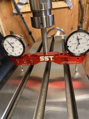
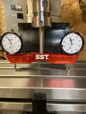
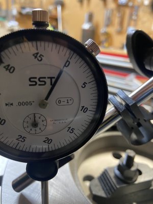
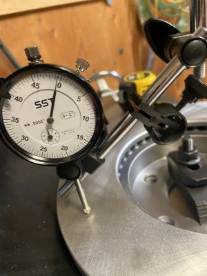
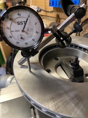
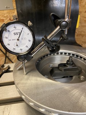
Well instead of submitting a word salad on how I did it the first time with the gauge set I went and grabbed a rotor and just redid the procedure, the new pictures tell the tale. I will say I didn't change much other than skipping over the T slots in the bed. I started with the NOD first then the left to right tilt, as for the shims well, there are none.

The rotor is the cats ass for ease of operation, bolt tightness is done by sneaking up on tight as every small wrench movement makes a movement until you get to almost tight enough. I thought for sure I was going to need to shim the NOD but the dial tells the tale. I however did chase the dial around the other night with shims and ended up pulling them out of the rear of the head. Started all over again with the gauge set as posted above this morning and then ended up trying the rotor method a few minutes ago.
 

Attachments

  • IMG_6922.JPG
    IMG_6922.JPG
    1.6 MB · Views: 1
  • IMG_6921.JPG
    IMG_6921.JPG
    1.7 MB · Views: 1
  • IMG_6920.JPG
    IMG_6920.JPG
    2 MB · Views: 1
  • IMG_6919.JPG
    IMG_6919.JPG
    2.1 MB · Views: 1
Hi MM,

Before you start chasing your own tail, take the holding clamp off the rotor and just sit it on the table, the other way up making sure that the surfaces are clean. Now checking the nod is just a matter of comparing the readings from the back to the front of the rotor.

As far as the column clamp bolts are concerned look up the torque rating for the bolts and this is the value that you use to tighten them to. No more no less, for every iteration this is the value that you will use.

The same technique is used for the head tram along the table. If your mill uses one or two securing bolts then it might need the three hole modification.

As far as the two dial gauge tram tool is concerned both gauges need to be set to zero at the same point on the table. Now you can use the tool to set the tram.
 
Well instead of submitting a word salad on how I did it the first time with the gauge set I went and grabbed a rotor and just redid the procedure, the new pictures tell the tale.

Good way to put it. But I don't know what you know. The word salad has a purpose. The photos help a lot.

I agree with @BaronJ with just a few additional points:

Flip the rotor over so the entire flat disk is sitting on the table. You are not machining the disc so it doesn't need to be clamped. The indicator applies virtually zero force. Just clean the table, clean the disc, and set it down flat on the table. If you have precision 123 blocks, you can make a tripod to set the disk on. Tuck two at the front and back on one side, and one in the middle on the other side, to form a tripod. This minimizes the chances that a small ding in your table will influence the results. I use homemade 246 blocks so I can leave my vise in place.

Insert thought - your table should also be stoned before ramming.......

Also, adjust the indicator holder linkage so the indicator sweeps the outside of the disk surface - say 1/4" in from the edge. This maximizes the displayed difference.

As far as the two dial gauge tram tool is concerned both gauges need to be set to zero at the same point on the table. Now you can use the tool to set the tram.

This is the point I was after @MooseMeat. If the two gauges are not calibrated to each other, the results are meaningless.

Your recent photos only show one gauge so a calibration is not needed.
 
Good way to put it. But I don't know what you know. The word salad has a purpose. The photos help a lot.

I agree with @BaronJ with just a few additional points:

Flip the rotor over so the entire flat disk is sitting on the table. You are not machining the disc so it doesn't need to be clamped. The indicator applies virtually zero force. Just clean the table, clean the disc, and set it down flat on the table. If you have precision 123 blocks, you can make a tripod to set the disk on. Tuck two at the front and back on one side, and one in the middle on the other side, to form a tripod. This minimizes the chances that a small ding in your table will influence the results. I use homemade 246 blocks so I can leave my vise in place.

Insert thought - your table should also be stoned before ramming.......

Also, adjust the indicator holder linkage so the indicator sweeps the outside of the disk surface - say 1/4" in from the edge. This maximizes the displayed difference.


This is the point I was after @MooseMeat. If the two gauges are not calibrated to each other, the results are meaningless.

Your recent photos only show one gauge so a calibration is not needed.
The gauges are calibrated but I showed the reading just off zero (first post on the red gauge) so I could see the difference and then minus one lite reading from the other heavy reading, could have left it at zero but I wanted to see a positive reading on both.

I'll try the loose rotor method today and see what I come up with, a point to note on these mills, the NOD is a three bolt pattern and the tilt is two in the front and two in the back by the motor.

Even know the bolts are all quite snug if you put your hand on the rim of the cast base that encloses the the pulleys at the front and pull down you can influence the dial gauge, so I think it's all good to be as accurate as possible from the start, however any tool pressure will change your zero.


On the "stoning" what type of stone is recommended and an oil stone I'm presuming?
 
Just my opinion...used brake rotor should never be used for accuracy line-up, they will inevitably have a certain amount of "heat warp" that makes then a bad choice.
The rotor is a new one, I am a little skeptical even of new parts, they have runout as well but I see many people using them, or one can source a tramming ring, haven't seen one on amazon yet, I personally like just using the table, after all that is your real reference point, but the rotor is very convenient I will say.
 
Even know the bolts are all quite snug if you put your hand on the rim of the cast base that encloses the the pulleys at the front and pull down you can influence the dial gauge, so I think it's all good to be as accurate as possible from the start, however any tool pressure will change your zero.

You are noticing something that I preach about often. The simple fact is that "everything is rubber". It really doesn't matter how big or how strong it is. Things always move in response to a force. It is not if, it is only how much. Good on you for noticing.

The rotor is a new one, I am a little skeptical even of new parts, they have runout as well

I think we have already danced around the "I don't give a rat's ass about what they say on the internet......" thing! LMAO!

This is simple. Test it. I deliberately bought a 12" disk rotor so I could put in my lathe - both to polish it and to test it. The front and rear runout of a new rotor should be in the 0.0005 or less range. If it isn't, return it and buy a better one. It doesn't have to be zero at the hub. But the front and back should be essentially zero at the disk.

I personally like just using the table, after all that is your real reference point, but the rotor is very convenient I will say.

Yes, the table is the real reference. But tables are seldom perfect. And those T-Slots are pure hell on an indicator. But the real advantage of the disk is the bigger extension front and back for nod. And being able to clear your vise.

On the "stoning" what type of stone is recommended and an oil stone I'm presuming?

I like the Norton round stones with honing oil. But they can be used dry too.


Dedicate a stone to your mill table and don't use it anywhere else. Look for little shiny spots where the stone cuts and get rid of them. A video here would be nice.
 
Hi MM,

Before you start chasing your own tail, take the holding clamp off the rotor and just sit it on the table, the other way up making sure that the surfaces are clean. Now checking the nod is just a matter of comparing the readings from the back to the front of the rotor.

As far as the column clamp bolts are concerned look up the torque rating for the bolts and this is the value that you use to tighten them to. No more no less, for every iteration this is the value that you will use.

The same technique is used for the head tram along the table. If your mill uses one or two securing bolts then it might need the three hole modification.

As far as the two dial gauge tram tool is concerned both gauges need to be set to zero at the same point on the table. Now you can use the tool to set the tram.
update single dial gauge;

laid the rotor flat on the table and it is still 0's all the way around, then I checked the table as well on it's own, same, 0's. I then chucked the rotor up in the lathe and put a dial on it, quite flat I will say, .0005 out if I read it right, so that actually transfers to the mill measurement, SHL? (shite house luck) or what.

Stones;
I'm into a good stoning but the thing is new, would not hurt as I actually dropped a tool on the bed and it left a few marks.

did I say you all are awesome here before?
 
and put a dial on it, quite flat I will say, .0005 out if I read it right,

That seems high for a new rotor. LOL. I'm actually serious!

I bet that is runout and its all due to setup. If you put two indicators on it at once, one front and one back, I bet they read the same within 2 tenths.

In other words, it will be even better on the mill.....
 
That seems high for a new rotor. LOL. I'm actually serious!

I bet that is runout and its all due to setup. If you put two indicators on it at once, one front and one back, I bet they read the same within 2 tenths.

In other words, it will be even better on the mill.....
it was .0005/ish out on the lathe as with the mill, figured the lathe validated the mill, 😉 should I be happy, I'm thinking so, what should I be aiming for for accuracy.

I'd invite you over for beers and some shop talk, maybe good Scotch is your thing, I'm easy as stated by my wife......
 
Back
Top