• Spring 2024 meetup in Calgary - date Saturday, April 20/2024. discussion Please RSVP Here to confirm and get your invitation and the location details. RSVP NOW so organizers can plan to get sufficient food etc. It's Tomorrow Saturday! you can still RSVP until I stop checking my phone tomorrow More info and agenda
  • We are having email/registration problems again. Diagnosis is underway. New users sorry if you are having trouble getting registered. We are exploring different options to get registered. Contact the forum via another member or on facebook if you're stuck. Update -> we think it is fixed. Let us know if not.
  • Spring meet up in Ontario, April 6/2024. NEW LOCATION See Post #31 Discussion AND THE NEW LOCATION

Jswain's active projects

Jswain

Joe
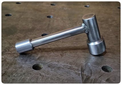
Nice chuck key Jeo.
Thanks for dharing your tramming procesure and results.

How ever. This spinning and measurements off the table is for the head tram and nod. Did you do a column tram as well?

Thanks !
I have not tried a column tram yet, that's probably a good idea.

How are you doing yours?
 

Jswain

Joe
Isn't that the same thing as head tram and nod????

What am I missing?
I think it would be if you wanted to shim the base of the column to remain square when adjusting z up and down.

I believe you need a long precision piece standing straight up on table and shim column to keep indicator on 0

Nod would be adjusted by shimming the swivelling portion of the head I believe. Which I did not do either as my indicator was reading the same front to back

But unsure as I've never done it
 

Susquatch

Ultra Member
Administrator
Moderator
Premium Member
I think it would be if you wanted to shim the base of the column to remain square when adjusting z up and down.

I am in unfamiliar territory.....

But it seems to me the only way it could change as the head is raised or lowered is if the column was bent. That's a MUCH bigger problem than Tramming.

Now, if we are talking slight x&y translations as the head is lowered and raised, that's a different matter. I don't think I've ever seen that discussed anywhere before. It might be one of those things you almost have to live with. Boy, talk about a dogs breakfast......
 

Jswain

Joe
I am in unfamiliar territory.....

But it seems to me the only way it could change as the head is raised or lowered is if the column was bent. That's a MUCH bigger problem than Tramming.

Now, if we are talking slight x&y translations as the head is lowered and raised, that's a different matter. I don't think I've ever seen that discussed anywhere before. It might be one of those things you almost have to live with. Boy, talk about a dogs breakfast......
Ive seen on the interwebs people shim or epoxy the base to make the column straight. I think it would highly depend on the mill/quality of casting/what day it came from the factory.

Beyond what I'm willing to get after at the moment lol
 

Susquatch

Ultra Member
Administrator
Moderator
Premium Member
Ive seen on the interwebs people shim or epoxy the base to make the column straight.

Ya, lots of guys do that. Some use shims. But that's usually done to fix nod not z-related changes.

Not saying it couldn't do Z related changes, but I've never seen or heard of anyone doing that. It would be a dogs breakfast.

It would be almost as bad as changing the Z-tram on a knee mill. It can be done, but holy crap. I wouldn't bother.
 

Proxule

Ultra Member
The column tramming in X and Y plane. Is so when you move your head up and down on the z axis. As I understand it.

I am using a precision granite square and hoping back and forth between X and Y wile shimming the column base.

Once you are happy. You move onto the head. You can adjust the tram on the X easy as our RF45 can rotate. But for the Y nod, we would have to shim the head between the Z axis sliding attachment, the saddle ( the portion that holds the gib strip ). If that makes sense to you Joe.
 
Last edited:

Susquatch

Ultra Member
Administrator
Moderator
Premium Member
The column tramming in X and Y plane. Is so when you move your head up and down on the z axis. As I understand it.


OK, but how do you do that without already having nod and rotate done, anything you put on the bed would indicate a false reading.

I am using a precision granite square and hoping back and forth between X and Y wile shimming the column base.

Once you are happy. You move onto the head.

The way I understand this, this would have to be done first, not last or you end up chasing your tail.

If it's done first, you still end up have to change the Z tram which throws out the x/y.

A never ending circle.

I'd be inclined to live with any Z error that exists. It's not any different than a Bridgeport. If I had that error I'd just accept it and move on. At worst, I'd measure it and take it onto account.
 

Jswain

Joe
This pretty much puts everything I am thinking into words and visuals!
That's a good video, thanks I saved it for the future. I may test with a 123 block that's about as long as a precision straight edge I have for now.
I'd be inclined to live with any Z error that exists. It's not any different than a Bridgeport. If I had that error I'd just accept it and move on. At worst, I'd measure it and take it onto account.
Probably will be best for me for now

In the very near future I plan on pulling x/y apart to clean & get rough measurements for making a new x axis nut.

When I get it back together perhaps I can check column tram
 

Jswain

Joe
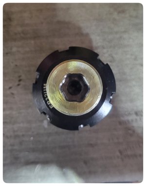
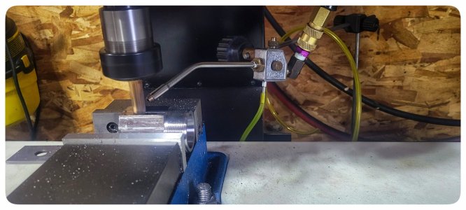
Well the mill was a little jealous that the lathe got a new chuck key. So I attempted to make one for it, but not everything works out.

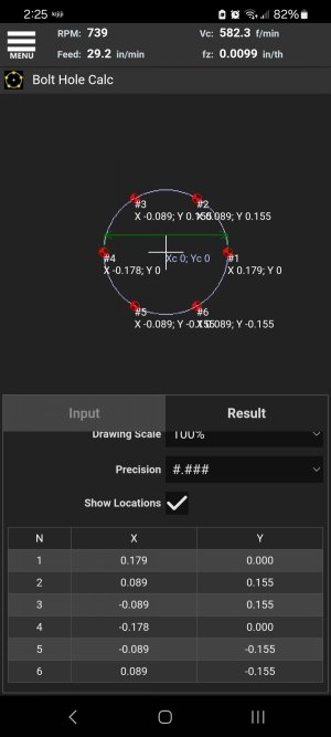
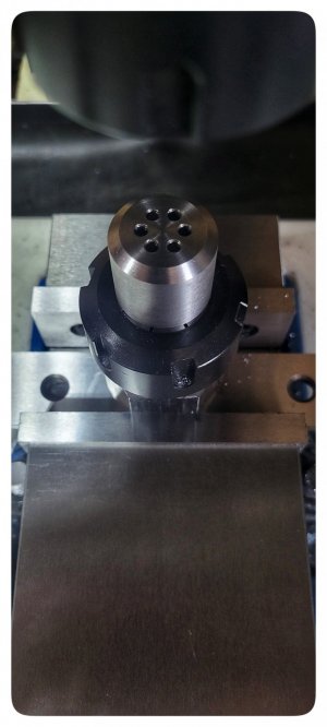
I used the bolt hole feature on the fswizard app and navigated with my dro(it doesn't have the bolt hole feature).

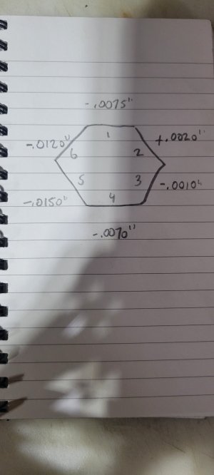
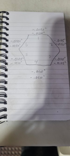
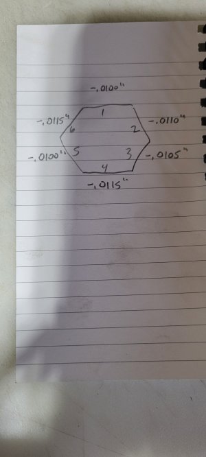
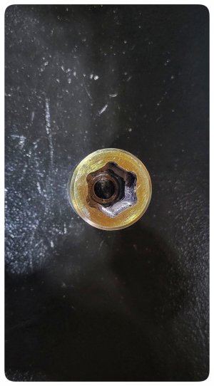
That portion went well but when I connected the dots you can see it wasn't even. I believe this is probably due to the hex er32 collet block not being concentric to the bore.

So now I will see If I can do the same as the square er32 block to improve that, then retry the internal hex cut to see how much of a difference it makes.
 

Attachments

  • Screenshot_20240309_142512.jpg
    Screenshot_20240309_142512.jpg
    124.1 KB · Views: 7
  • 1000006387-01.jpeg
    1000006387-01.jpeg
    815 KB · Views: 7

Jswain

Joe
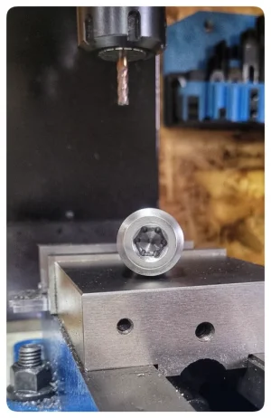
Getting much better, think I will try dusting up the 1 highest side and hopefully leaver b. I took the first measurements then rotated the collet 180 degrees for the second measurements, so I believe most of the runout is still in the block.

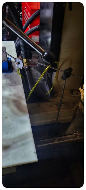
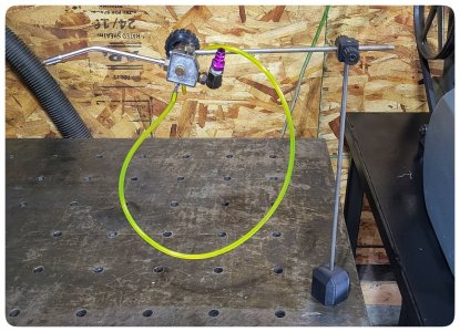
This one is much harder then the square was. Pulled out the mister and just used it with air which I quite liked so I may come up with a good mount for the mill & have it somewhat always rigged in.

You can see the homemade mag base I cobbled together with 3d printed parts. I got the mister with the South bend and figured it would come in handy someday.
 

Attachments

  • 20240310_114100.jpg
    20240310_114100.jpg
    180.4 KB · Views: 7
  • 1000006403-01.jpeg
    1000006403-01.jpeg
    295.4 KB · Views: 7
  • 1000006405-01.jpeg
    1000006405-01.jpeg
    231.2 KB · Views: 7

Proxule

Ultra Member
OOOOooo. A mist setup. Can you elaborate ? Lol

Nice work, I have a Chineseum hex block that is just as sick as yours.

Thanks !
 

Jswain

Joe
OOOOooo. A mist setup. Can you elaborate ? Lol

Nice work, I have a Chineseum hex block that is just as sick as yours.

Thanks !
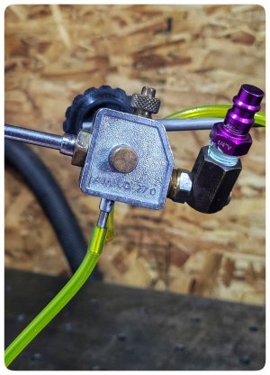
It's an amflo 270 coolant mister. Hook it up to air and shove the hose in your coolant(or just use air) and you can adjust both the airflow & coolant flow to mist the tool without the mess of flood cooling.

You can get a generic one on Amazon for very cheap, like $20 or something

And you can see my homemade "mag base" better here
 

Attachments

  • 1000006412-01.jpeg
    1000006412-01.jpeg
    664.1 KB · Views: 7
  • 1000006411-01.jpeg
    1000006411-01.jpeg
    511.8 KB · Views: 8

Jswain

Joe
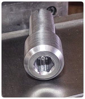
The hex er32 collet block turned out better then I could hope(realizing if it's out front to back I still have yet to fix that issue)
 

Attachments

  • 20240310_132017.jpg
    20240310_132017.jpg
    189.4 KB · Views: 3

Jswain

Joe
Definitely much better. Not wanting to waste anymore scrap to find out it wasn't going to work i went up to the next size I figured may be handy.

I will need to make a vise stop for repeat positioning of the block when I rotate it but other then that I'm thinking it will be good.
 

Attachments

  • 1000006418-01.jpeg
    1000006418-01.jpeg
    295.6 KB · Views: 8
  • 1000006419-01.png
    1000006419-01.png
    867.3 KB · Views: 8

Jswain

Joe
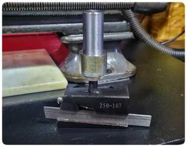
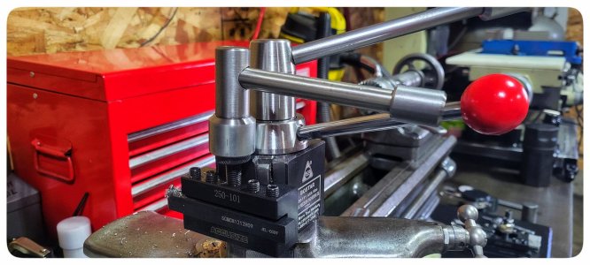
Not bad for a mishap. Halfa$$ matches the chuck key. I'm a sucker for having the tools needed for the machine at the machine so I think it will live next to the tool centre height standard.

Just gotta make one for the mill vise now.
 

Attachments

  • 1000006426-01.jpeg
    1000006426-01.jpeg
    331.7 KB · Views: 9
  • 1000006427-01.jpeg
    1000006427-01.jpeg
    230.9 KB · Views: 9
  • 1000006428-01.jpeg
    1000006428-01.jpeg
    472.5 KB · Views: 9

Susquatch

Ultra Member
Administrator
Moderator
Premium Member
I'm a sucker for having the tools needed for the machine at the machine so I think it will live next to the tool centre height standard.

That is NOT being a sucker. I think that's wise, efficient, and even necessary. Imagine mounting a chuck, holding it on with one hand, and then the chuck key is out of reach..... Not good.
 
Top