• Scam Alert. Members are reminded to NOT send money to buy anything. Don't buy things remote and have it shipped - go get it yourself, pay in person, and take your equipment with you. Scammers have burned people on this forum. Urgency, secrecy, excuses, selling for friend, newish members, FUD, are RED FLAGS. A video conference call is not adequate assurance. Face to face interactions are required. Please report suspicions to the forum admins. Stay Safe - anyone can get scammed.

Jswain's active projects

Don't worry about a brake Sus, it would never work for you anyway. Could you imagine clearing your welding table off so you coud put a sheet on it for bending ?:confused:

Good point.......

But maybe that isn't really that big an issue. I figure it will have to go in the barn yard someplace anyway cuz there in no room inside for a table unless a tractor goes outside and that isn't happening. Since an outside table would be visible to the bride from the yard, you can rest assured that it will never have anything on it.

I know it's sacrilege to put a welding table outside, but that's the way it's gunna hafta be. I'm resigned to having a rusty old table someday.

Who else has theirs outside?

Does the rust matter? How about a few big stainless studs on the insides of the 4 legs to put the ground cable on?

And how would a rusty table affect a sheet metal brake?
 
That power feed module.... I'm thinking it might be a good alternative for driving the lead screw on my mini-lathe. I just don't like the gear train running off the spindle drive.

How is the one you have working out for you??
The one I have had been so far flawless. I haven't used it much recently, but after installing I did use it quite a bit.
 
I just don't like the gear train running off the spindle drive.

That is the common way of doing it. A set of gears linking the lead screw to the spindle is an excellent and common way to mechanically achieve an exact thread pitch.

There are electronic (ELS) ways to do it too.
 
That is the common way of doing it. A set of gears linking the lead screw to the spindle is an excellent and common way to mechanically achieve an exact thread pitch.

There are electronic (ELS) ways to do it too.
Yup. I've seen people integrating power feeds for threading but it's complicated programming and I'm not up for that. I'll tap any threads I need and avoid the larger diameter stuff... or use the gears. My machine is underpowered in low-end torque as it is so having the gears off is better - and quieter.

I'm more interested in the "speed and feed" options for achieving smoother finishes. I'm just now learning how how important that is.... it's really tricky to do it manually. So having control over feeding the tool along the workpiece should make for a better finish. That's what I imagine anyways..
 
it's really tricky to do it manually. So having control over feeding the tool along the workpiece should make for a better finish. That's what I imagine anyways..

My opinion will not be popular.

I think learning to do it manually in a smooth consistent repeatable manner is a very important skill to acquire. It isn't as hard as you might think. It's all in how you use your two hands to turn and control the wheel. Practice makes perfect.

I'm actually MUCH MORE afraid of getting a motorized system to do as well automatically as I can do manually than I am about doing a good job manually.
 
Been awhile since I posted any updates here. And it will be much slower then before with me back working on the road but should give me some motivation to get some shit done.

New additions to the shop since the last updates

Hopefully near future projects will be:

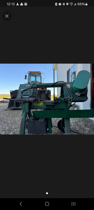
The bandsaw needs a coolant reservoir cover, and an upper blade cover to replace the broken plastic factory unit. Probably make both out of some sheet steel

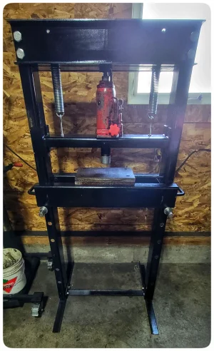
Shop press will get a press brake. Undecided if I will do a finger style or just straight 1 piece. TBD. After that I'll probably be looking for an air - hydraulic jack but I may keep this one until it fails.
 

Attachments

  • 1000008177.webp
    1000008177.webp
    342.2 KB · Views: 13
  • Screenshot_20240622_121331.webp
    Screenshot_20240622_121331.webp
    80.3 KB · Views: 13
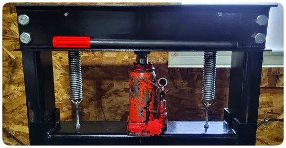
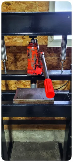
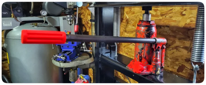
Found a mostly straight pipe that fits perfect for a jack handle. 3d printed a handle for it to slow me down from using it elsewhere
 

Attachments

  • 1000008194.webp
    1000008194.webp
    299.8 KB · Views: 6
  • 1000008192.webp
    1000008192.webp
    233.1 KB · Views: 5
  • 1000008193.webp
    1000008193.webp
    224.1 KB · Views: 5
Found a mostly straight pipe that fits perfect for a jack handle.

I make and use black pipe handles for most of my bottle jacks including the one I use in my press.

The problem is that the handles that come with the jack fit like crap, are usually too short, and don't usually have a good fit to the release valve either. So I make my own out of the appropriate size black pipe.
 
Small update, picked up some 16g sheet to make some covers for the bandsaw.

Started with some scrap angle & made the coolant tank cover. Holds a Scotch Brite pad underneath to keep the oil mostly clean. The box was already made and seems to work so didn't see a reason to change anything other then making the lid.

For convenience I added a longer power cord to the saw, it originally just had a 12" piece with a plug end and I hate extension cords if I don't need them.

While I was in there I added a male and female plug end to the coolant pump so I can shut it off when wanted as there was no switch inline.

Will start on the blade covers tomorrow hopefully.
1000008374.jpg
1000008375.jpg
1000008377.jpg
1000008378.jpg
1000008376.jpg
 
Last edited:
Added a small tube to the top of the lid, and used a hole saw to cut a 1"ish hole in the plate under the scotchbrite to let it flow better. It's tight enough to the top tray now if that doesn't let it flow enough to not leak I'll just omit the scotchbrite in the cover & leave the piece in the tray up top. So far so good though.

Then got cracking at the top blade cover. There's not really a good handle on the saw so I can see it now inadvertently getting fingers in the blade lifting it if it's still running. Pretty happy with the fitup, except for the hole in the centre is a little off, not bad for winging it.

I think I will build some sort of form tool for the press to make a formed cover to weld over the hole, we'll see...going to make the bottom blade cover first. Should help direct all the oil back to the pan as well.

Might weld a handle to the top guard as well, don't really want to weld to the frame of the saw.
1000008392.jpg
1000008391.jpg
1000008390.jpg
1000008388.jpg
 
If you don't like barnyard fab look away. Was initially going to 3d print a dimple die but for 3" it'd be like 8 hours each top and bottom so f waiting.

Looked around the shop. Found a couple suitable things that looked like they would enjoy being pressed and went to town

It didn't turn out perfect, like usual. But gave me some breathing room on the inner pulley and made the 16g sheet stiffer, was oil canning a bit after welding. I was scared it would press offset, not being keyed to the bottom die, and it did. But a little massaging with a flap wheel and it looks ok, better then the broken plastic guard / nothing.
1000008396.jpg
1000008397.jpg
1000008398.jpg
 
Nice work!

Nothing wrong with a little back yard tooling. I’ve been known to break out the red neck bending break (angle iron, 2 x 4s and an 8 lb hammer) now and then when I need some sheet metal adjusted. ;)

D :cool:
 
I recently picked up the same Vevor for my RF45 and have been trying to figure how to install it. Great information from this site. The only thing I think I will do is weld an extension on the lead screw, a couple of inches long on what will now be the motor end or Right side looking at the machine I will do this while the lead screw is out. Bevel and weld a 3/4 inch diameter rod on the end of the lead screw end, then turn it down to the correct diameter of the lead screw which is around 5/8 inch. Doing that modification will allow room for the brass gear, and the hand crank using the original parts.
That way if the Vevor burns out, I can simply put everything back together as original.
Let me know if you see any problems with that idea.
Also, what thickness is your new plate for the new lead screw support plate. It looks like 1/2 inch.
Does anyone have a sketch or measurements for the round brass gear cover. I should be able to figure it out easily enough, but if someone has it that is great.
Thanks for your help Grant
 
Hi Grant. Joe may have done it a different way. I would look at making an adapter with set screws to extend the lead screw rather then welding. I am curious as to why there is no adapter in the power feed set? Id there a difference in the drive gear as to the lead screw?

With my power feed I have the vertical unit. I modified the brass drive gear to fit my lead screw, filed a flat on the lead screw for the grub screw on the drive gear. I modified a plate for the bearing on that side. Originally it was just a bushing in the cast aluminum piece. Drilled holes to mount the drive and done. If you have the horizontal one it should be easier, but I could be wrong.
 
I recently picked up the same Vevor for my RF45 and have been trying to figure how to install it. Great information from this site. The only thing I think I will do is weld an extension on the lead screw, a couple of inches long on what will now be the motor end or Right side looking at the machine I will do this while the lead screw is out. Bevel and weld a 3/4 inch diameter rod on the end of the lead screw end, then turn it down to the correct diameter of the lead screw which is around 5/8 inch. Doing that modification will allow room for the brass gear, and the hand crank using the original parts.
That way if the Vevor burns out, I can simply put everything back together as original.
Let me know if you see any problems with that idea.
Also, what thickness is your new plate for the new lead screw support plate. It looks like 1/2 inch.
Does anyone have a sketch or measurements for the round brass gear cover. I should be able to figure it out easily enough, but if someone has it that is great.
Thanks for your help Grant
Swap your leadscrew and the original plates end for end around and the long side will be on the side you want to mount the power feed. No welding required!

I believe my plate started out as 3/4" and then machined down. I can send you .STL or any fusion files for both the plate & then cover when I get back home in the next week or so.

There is also a good writeup here from @DavidR8 and @YYCHM

Check them out, they installed theirs on rf30? I believe but basically same process.

But if you swap the leadscrew & plates so the long end is on the power feed side, all you need to do is make a mounting plate, bore the brass gear slightly to fit on the leadscrew, then trim it to length. Drill and tap the brass gear for set screws. And then figure out your limiter switch etc.

I think that's all but it's been a little while..
 
I recently picked up the same Vevor for my RF45 and have been trying to figure how to install it. Great information from this site. The only thing I think I will do is weld an extension on the lead screw, a couple of inches long on what will now be the motor end or Right side looking at the machine I will do this while the lead screw is out. Bevel and weld a 3/4 inch diameter rod on the end of the lead screw end, then turn it down to the correct diameter of the lead screw which is around 5/8 inch. Doing that modification will allow room for the brass gear, and the hand crank using the original parts.
That way if the Vevor burns out, I can simply put everything back together as original.
Let me know if you see any problems with that idea.
Also, what thickness is your new plate for the new lead screw support plate. It looks like 1/2 inch.
Does anyone have a sketch or measurements for the round brass gear cover. I should be able to figure it out easily enough, but if someone has it that is great.
Thanks for your help Grant
On my RF30 mill I mounted the powerfeed horizontally on the left side of the table. I flipped lever so that it pointed toward the front of the table.
Worked very well.
I'll see if I can find the link to the post.
@Grant T Here's a link to the posts where I'm installing the power feed: https://canadianhobbymetalworkers.com/threads/davidr8s-shop-shenanigans.2767/post-39176
 
Last edited:
Back
Top