-
Scam Alert. Members are reminded to NOT send money to buy anything. Don't buy things remote and have it shipped - go get it yourself, pay in person, and take your equipment with you. Scammers have burned people on this forum. Urgency, secrecy, excuses, selling for friend, newish members, FUD, are RED FLAGS. A video conference call is not adequate assurance. Face to face interactions are required. Please report suspicions to the forum admins. Stay Safe - anyone can get scammed.
-
Several Regions have held meetups already, but others are being planned or are evaluating the interest. The Calgary Area Meetup is set for Saturday July 12th at 10am. The signup thread is here! Arbutus has also explored interest in a Fraser Valley meetup but it seems members either missed his thread or had other plans. Let him know if you are interested in a meetup later in the year by posting here! Slowpoke is trying to pull together an Ottawa area meetup later this summer. No date has been selected yet, so let him know if you are interested here! We are not aware of any other meetups being planned this year. If you are interested in doing something in your area, let everyone know and make it happen! Meetups are a great way to make new machining friends and get hands on help in your area. Don’t be shy, sign up and come, or plan your own meetup!
You are using an out of date browser. It may not display this or other websites correctly.
You should upgrade or use an alternative browser.
You should upgrade or use an alternative browser.
Installing a DRO on a Hartford Bridgeport Clone.
- Thread starter Susquatch
- Start date
This morning I tackled the Y-Axis. Zero problems drilling the knee. Well, I say zero, but not really. It drilled with regular HSS just fine, but the casting was quite thin where I chose to drill it. Didn't leave much for putting a screw in. Perhaps worse, when I added the scale, I discovered that the knee had a convex surface where I chose to put the scale so I had to use the tiny little grub screws built into the scale ends - they are there for that purpose.
Anyway, now the Y Axis Scale is installed, levelled, and properly aligned.
Next up is the read head bracket. The bottom of the table apron has a slight 10° slope to it. So I cut a piece of bar stock off with a 15 degree angle cut right into it from the git-go.
Now I have to figure out how to machine the rest of the features into the bracket piece with that dumb angle in it...... But I do get to use a working X-Axis DRO to help me do it!
Last edited:
You could always put some bondo or something like it behind it I just went with the screw adjusters.
I won't know for sure till I get the read head installed. I want to try and do that yet today.
If it doesn't work, I might put something like bondo or wood filler behind it. For now it tests ok.
Finished the Y-Axis Read Head Bracket after working on taxes enough to keep the bride happy.

The back recess and 5 degree angle are to accommodate the slight contour of the bottom of the saddle below the right x-axis crank.

The one screw is slightly hidden by the sensor cable, but I figured it was more important to have the screws line up than it was to have perfect access. There is plenty of access there for an Allen wench. Besides, the bracket can be mounted before the sensor is attached if need be.
Tomorrow I drill two screw holes in that ultra hard cast iron that the table and saddle are made from. I'm not looking forward to it. Not just because the metal is so hard, but also because it has to be done from the bottom looking up and old men like me are just not all that flexible as they once were.
The back recess and 5 degree angle are to accommodate the slight contour of the bottom of the saddle below the right x-axis crank.
The one screw is slightly hidden by the sensor cable, but I figured it was more important to have the screws line up than it was to have perfect access. There is plenty of access there for an Allen wench. Besides, the bracket can be mounted before the sensor is attached if need be.
Tomorrow I drill two screw holes in that ultra hard cast iron that the table and saddle are made from. I'm not looking forward to it. Not just because the metal is so hard, but also because it has to be done from the bottom looking up and old men like me are just not all that flexible as they once were.
Finished drilling and tapping the saddle for the Y Axis bracket. Same issues as before, but patience and carbide held the line.
Here is the finished install.

Just need a cable relief and I may do a shield.
I definitely discovered that the magnetic scales do not like swarf. You can even see the 2mm magnetic pitch!

Here is the finished install.
Just need a cable relief and I may do a shield.
I definitely discovered that the magnetic scales do not like swarf. You can even see the 2mm magnetic pitch!
Somewhere in one of my posts I mentioned pre-drilling mounting plates for adjustment set screws to compensate irregular surfaces or slightly angled (draft casting) surfaces. I'll use your picture as example. Imagine each corner has a tapped hole & set screw. Now you can lightly tighten the main cap screws but micro adjust the plate orientation so the scale is aligned & fine tune it. Its a lot easier than messing with shims. One day you may have to dismantle DRO for whatever reason & you will stand a better chance, or at least easier job of good alignment again. If you feel you want full contact, you could put release film on the casting to protect the Chinese Tremclad & slow set filled epoxy to grout the plate in place. Relieving the mid section the way you did was a good thought.
Attachments
Last edited:
Somewhere in one of my posts I mentioned pre-drilling mounting plates for adjustment set screws to compensate irregular surfaces or slightly angled (draft casting) surfaces. I'll use your picture as example. Imagine each corner has a tapped hole & set screw. Now you can lightly tighten the main cap screws but micro adjust the plate orientation so the scale is aligned & fine tune it. Its a lot easier than messing with shims. One day you may have to dismantle DRO for whatever reason & you will stand a better chance, or at least easier job of good alignment again. If you feel you want full contact, you could put release film on the casting to protect the Chinese Tremclad & slow set filled epoxy to grout the plate in place. Relieving the mid section the way you did was a good thought.
Yes, I saw that suggestion but misunderstood it. I seem to do that a lot with you. I guess I just need to make a mental note of that to pay more attention to what you write.
At the time I read your earlier note, I actually replied that my scales have that feature built in. This is the latest "slim" scales. The older magnetic scales were better for that with 4 corner grub screws.

But now I see that you are referring to the read head bracket, not the scales. Again, sorry I misread that earlier.
That's a good idea. It's the same principle but applied to the other half of the system.
You had also suggested a filler. I may do that (too). I like two part wood filler (eg Minwax High Performance Wood Filler) for that purpose. It's cheaper and more forgiving than regular epoxy and can be much more easily machined with simple tools (chisels, files, etc) if necessary. It's also very solid. Either way, shoe wax makes a great release agent.
To be honest, I didn't even notice that gap. Old men don't see well or in my case bend over to see it at all! What happens below my waist is usually ignored unless it is painful or enjoyable. The mount is pretty solid despite it. But now it will bug me till I fix it. Thanks a whole lot for pointing that out....... 😉
No worries. Just wanted to point out relatively easy fixture feature that might help with DRO setup. Casting surfaces & drilled mounting holes are typically not great to mount things to in a precise , repeatable manner. And some DRO systems are less tolerant of misalignment or flex.
No worries. Just wanted to point out relatively easy fixture feature that might help with DRO setup. Casting surfaces & drilled mounting holes are typically not great to mount things to in a precise , repeatable manner. And some DRO systems are less tolerant of misalignment or flex.
Still, I owe you an apology for jumping to conclusions. I've said this before: I've observed that you often put a lot of effort into helping others, and sometimes I skim over it because it's more than I feel like I know where you are going. It's a side effect of dealing with technical people and academics all my life. However, it's an injustice to you and I'm sorry for doing it.
Please accept my apology because I'm pretty sure it will happen again. When it does, just keep going and attribute it to my advanced age, a life filled with way too much information and a learned shortage of patience. Then rub my nose in it a bit harder knowing I actually do appreciate it.
In this case, if I had read what you said more carefully, I might have made a much better mounting bracket and wouldn't have had to go back in there with wood filler to hide an embarrassing gap.
Nuff said.
Z-Axis is almost done.
X & Y are working fine. I used them both to make the Z-Axis Read Head Bracket. Very cool, but lots to learn and a few old habits need re-learning.
Here is the scale mounted. The base casting is horrible. So the scale is mounted on three pads of two part wood filler. I used shoe wax on the scale, but wanted it to stick to the base. So no wax there.

Here is the Z-Axis Read Head Bracket. All I have to do tomorrow is drill and tap the knee for the bracket mounting screws.


Big day tomorrow......
X & Y are working fine. I used them both to make the Z-Axis Read Head Bracket. Very cool, but lots to learn and a few old habits need re-learning.
Here is the scale mounted. The base casting is horrible. So the scale is mounted on three pads of two part wood filler. I used shoe wax on the scale, but wanted it to stick to the base. So no wax there.
Here is the Z-Axis Read Head Bracket. All I have to do tomorrow is drill and tap the knee for the bracket mounting screws.
Big day tomorrow......
Well, the big day and the big moment has arrived.
I have working X, Y, & Z Axis.

I deliberately mounted the Z Sensor so it "ALMOST" reaches the bottom of the scale so I have some scale left at the top. There is what looks like a travel limit at the top of the rear Z ways. I suspect that removing it might provide another 2 or 3 inches of travel - or the knee will fall off! Yikes!
I still need to dress the wiring, provide strain relief, and develop reasonable covers & shields. But it works the way it is.
I also did a quick run to both ends and back with a ball edge finder to ascertain repeatability under normal operating conditions for all three axis. They all work as expected.
So now I can take my time completing the rest of the system as well as learn how to use it better than I already have. There is so much to learn and old habits to break!
Last, but not least, this is a four axis system with RPM, so I also need to start planning a Quill scale to combine with my existing Z for a total Z number, and I need to figure out how the RPM System in this thing works so I can use a crank sensor on the drive gear with a conversion interface instead of the hall effect system that came with it. All TBD.
Very happy for now!
Many many thanks to everyone who chimed in and helped me get to this point. It was rough going at first so your help is appreciated more than you can guess!
I'll continue to post here as the system progresses.
I have working X, Y, & Z Axis.
I deliberately mounted the Z Sensor so it "ALMOST" reaches the bottom of the scale so I have some scale left at the top. There is what looks like a travel limit at the top of the rear Z ways. I suspect that removing it might provide another 2 or 3 inches of travel - or the knee will fall off! Yikes!
I still need to dress the wiring, provide strain relief, and develop reasonable covers & shields. But it works the way it is.
I also did a quick run to both ends and back with a ball edge finder to ascertain repeatability under normal operating conditions for all three axis. They all work as expected.
So now I can take my time completing the rest of the system as well as learn how to use it better than I already have. There is so much to learn and old habits to break!
Last, but not least, this is a four axis system with RPM, so I also need to start planning a Quill scale to combine with my existing Z for a total Z number, and I need to figure out how the RPM System in this thing works so I can use a crank sensor on the drive gear with a conversion interface instead of the hall effect system that came with it. All TBD.
Very happy for now!
Many many thanks to everyone who chimed in and helped me get to this point. It was rough going at first so your help is appreciated more than you can guess!
I'll continue to post here as the system progresses.
A while back, I bought a bag of cable clips to run Ethernet cables in the house. With modern WiFi, that was a waste.
But if I replace the wood screw with a machine screw, I should be able to dress all the cables and provide strain relief very nicely. The DRO cable is bit thicker than Ethernet cable but the clamp is adjustable enough to hold it just fine.
More drilling in undrillobillium..... 😵

But if I replace the wood screw with a machine screw, I should be able to dress all the cables and provide strain relief very nicely. The DRO cable is bit thicker than Ethernet cable but the clamp is adjustable enough to hold it just fine.
More drilling in undrillobillium..... 😵
Well, it's time to install the 4th (quill) axis on my Hartford Mill. I've taken months to get to it cuz I couldn't come up with an ideal design. Hartford would have fired me if I worked for them. A guy I worked for years ago once said: there comes a time in every project when you have to fire all the engineers and get on with production. Engineers are perfectionists and their own worst enemy at times.
So many compromises:
Access quill stop adjustment
Quill Scale Visibility
Rigidity of scales
Rigidity of sensor
Repeatability
Clear of quill feed wheel
Clear of Turret Face Lugs
Signal Cable Folding
Well, I think I have it nailed.
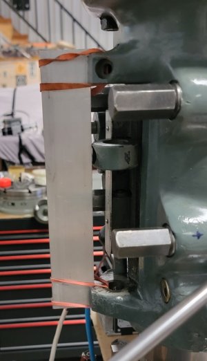
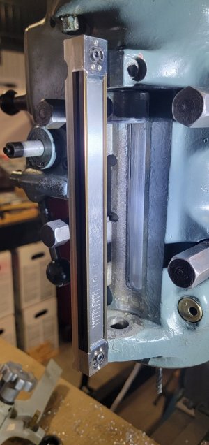
Here are some before and during photos.


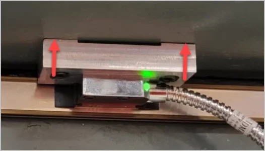
The read head will go on the quill indicator (see red arrow) in the photo below.

The Mount will look like this:
Please note that I'm standing on the church steps naked with this photo. It is the very first Fusion 3D solid model I have shown you guys. Please be gentle......

The threaded hole on top is for a 5/16 post to provide strain relief for the cable. The sensor attaches to the two small threaded holes. The hole in the curved surface is for a 1/4-28 screw to hold the fixture to the quill indicator. The bottom relief is to let the quill stops turn freely.
I also did my first shop drawing from the 3D model. Wow! Now that's a cool feature !!!
I'll prolly always do crude drawings right out of my head just because it's easy for me, but Fusion is so much more professional looking!
Move over @PeterT! LOL!! No worries Peter, at my ripe old age I'll be dead before I catch up to you!
So many compromises:
Access quill stop adjustment
Quill Scale Visibility
Rigidity of scales
Rigidity of sensor
Repeatability
Clear of quill feed wheel
Clear of Turret Face Lugs
Signal Cable Folding
Well, I think I have it nailed.
Here are some before and during photos.
The read head will go on the quill indicator (see red arrow) in the photo below.
The Mount will look like this:
Please note that I'm standing on the church steps naked with this photo. It is the very first Fusion 3D solid model I have shown you guys. Please be gentle......
The threaded hole on top is for a 5/16 post to provide strain relief for the cable. The sensor attaches to the two small threaded holes. The hole in the curved surface is for a 1/4-28 screw to hold the fixture to the quill indicator. The bottom relief is to let the quill stops turn freely.
I also did my first shop drawing from the 3D model. Wow! Now that's a cool feature !!!
I'll prolly always do crude drawings right out of my head just because it's easy for me, but Fusion is so much more professional looking!
Move over @PeterT! LOL!! No worries Peter, at my ripe old age I'll be dead before I catch up to you!
Attachments


One thing I've learned with DRO installation is that irregular casting surfaces can cause grief with the mount alignment & thus translate these issues into the DRO assembly. A good design feature to incorporate some threaded holes in key locations on mounting hardware for set screws (independent to the main mount fasteners). This allows micro-jacking alignment without shims & such. This pays dividends if you ever have to dismantle DRO & re-install.
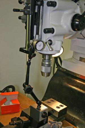
You probably know but just in case, rig up a test indicator & raise the knee to validate alignment DRO scale in 3 planes.
Are you going for a scale or a quill type readout? I installed a Mitutoyo quill model on mine but even on sale its a spendy bugger. The main reason was (impatience) Bridgeport style mounting components included which was relatively straightforward installation. If I did it again I would select the Accusize model (same unit as Shars & other sellers). Display is bigger, same features, same effort to install but probably have to make hardware. Dabbler ended up with mine, maybe he can comment on end result.
Attachments
I was thinking of doing this, plus it would allow the installation to be “generic” and not specific to a particular manufacturer.…A good design feature to incorporate some threaded holes in key locations on mounting hardware for set screws (independent to the main mount fasteners). This allows micro-jacking alignment without shims & such…
Hopefully I‘ll find out over winter… though I’m pretty slow so it may not be until next winter..
One thing I've learned with DRO installation is that irregular casting surfaces can cause grief with the mount alignment & thus translate these issues into the DRO assembly. A good design feature to incorporate some threaded holes in key locations on mounting hardware for set screws (independent to the main mount fasteners).
Also @StevSmar
My scales actually came with integral jacking screws for that purpose. If you look at the photo with the red arrow on it, you can see the three jacking screws on each end of the scale.
I guess for anyone who doesn't have magnetic scales, you might not have even noticed that the scale was actually already mounted in the photo.
I can't really check axial alignment till I get the sensor mounted. But another advantage of magnetic scales is relative insensitivity to alignment. In my experience, they will work relatively well with a misalignment (gap) that varies by about a 1/16 inch. Of course, I will shoot for whatever minimum axial and gap misalignment I can achieve.
You probably know but just in case, rig up a test indicator & raise the knee to validate alignment DRO scale in 3 planes.
Yes, I did. But in practice I found the magnetic scales to be virtually immune to minor misalignments. About the only thing I really HAD TO DO was to always set axial alignment. The rest seemed to make no difference that I could measure. Of course, one of the things about the 1 micron scales is that they are deadly accurate. Much more accurate than my tenths indicator. Mind you an alignment error doesn't show up that way so one could be easily fooled into believing numbers that are not really correct despite the number of digits.
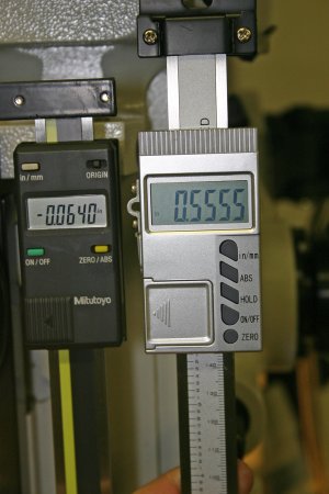
My Ditron can also be adjusted (calibrated) for distance related errors - both linear and non-linear. However, I found my other three axis to be dead-on.
Are you going for a scale or a quill type readout? I installed a Mitutoyo quill model on mine but even on sale its a spendy bugger. The main reason was (impatience) Bridgeport style mounting components included which was relatively straightforward installation. If I did it again I would select the Accusize model (same unit as Shars & other sellers). Display is bigger, same features, same effort to install but probably have to make hardware. Dabbler ended up with mine, maybe he can comment on end result.
You might want to look at earlier posts on my DRO install. I previously mounted the X, Y, and Z magnetic scales on the table, saddle, and knee of my mill.
But my Readout box has the ability to combine my quill with the knee to provide a total Z for both together.
So I am now mounting the quill scale on the quill. Again, if you look at the photo with the red arrow, you will see that the magnetic scale is already there. I just need to machine and mount my quill adapter for the read head (which is what is shown in the drawings). It might take a few more days owing to other family related priorities. But it's within striking range now.