• Scam Alert. Members are reminded to NOT send money to buy anything. Don't buy things remote and have it shipped - go get it yourself, pay in person, and take your equipment with you. Scammers have burned people on this forum. Urgency, secrecy, excuses, selling for friend, newish members, FUD, are RED FLAGS. A video conference call is not adequate assurance. Face to face interactions are required. Please report suspicions to the forum admins. Stay Safe - anyone can get scammed.

Installing a DRO on a Hartford Bridgeport Clone.

@PeterT & @StevSmar - this photo might help explain my answers to your questions and advice.

There are already two small machined pads on the quill indicator. The two flats and the two ledges on both pads seem to be quite well aligned to the spindle. See item 1 and 2 in the photo below. I used an indicator mounted on the table and then used the knee to check each of them in two planes (x&y). Checking X & Y at two different knee heights implies Z is ok too.

20210609_180311~2.jpg

I took the liberty of adding a 3rd arrow above to show where the read head will mount. If you are familiar with Bridgeport, this part slides up and down with the quill sleeve so it's a good spot (maybe the only spot) to mount the read head.

They are not perfect, but as I said earlier, the scale itself has 2 sets of jack screws, the scale has an adjustment slot (shown as A below), and I made the brackets with adjustment slots in the X direction for its mounting screws too (not shown on any of the photos).
20220903_102226~3.jpg

The scale as shown mounted above might not be well aligned yet. Visually, it appears to be, but I want to wait till the read head is mounted and working to make final adjustments using an indicator and the DRO itself. Slots in the scale bracket provide X adjustment and square. Slots in the scale provide Y adjustment and square (see A in the photo). And the jacking screws provide axial and twist alignment.

Also not shown in any of the photos are reliefs in the Angle Bracket for the quill indictator and stop hardware and to ensure a good fit into the top and bottom corners of the pads on the housing.

I'm pretty confident it's all covered. But one never knows for sure till its all done and calibrated.
 
Last edited:
Wooooo Hooooo! My Z-Axis Quill DRO is in!

20220908_105235.jpg

20220908_105327.jpg

Not enough room for a cable strain relief after all........ :(

Still need to calibrate and dress the cable. But it doesn't look like I'll need to use the jack screws at all. Everything appears to be square and aligned well to the eye. An indicator will tell the final story.

Here is the Display showing working Z (knee DRO) & U (quill DRO).

20220908_105408.jpg

And here is the display setup to combine Knee & Quill for a total Combined Z.

20220908_111738.jpg

Note the tiny little +Z beside U.

Here it is after moving the knee 1mm. As you might notice, the total is out by two hundredths of a mm. One could be rounding, the other might be alignment.

20220908_111818.jpg

I chose to display both Z and U+Z. I could have simply displayed Z+U as Z only but I sorta liked the idea of having a separate display for the knee.

The only thing left to do now is calibration, cable dressing, and the Tachometer. The tach will probably take a few years because it must wait for the next head disassembly when I can get at the final spindle drive to install sensor(s). I'll come back and update the thread when I get around to doing the tach.

An interesting side story. Unbeknownst to me, the quill indicator sits at a slight angle to the vertical quill axis. This was apparent to my naked eye when I test fitted the read head bracket. The bracket was sitting at a very slight angle. Worse, the plane of that angle was at yet another angle. Fortunately, I had not yet set the read head offset to be in line with, centered on, or square to the magnetic strip. So I milled the read head mounting surface last. To get the required complex angle plane, I had to put the bracket into a small grinding vise, which was mounted in a bigger sine vise, which was mounted in my milling vise. It was a geometry setup nightmare. Obviously required multiple checks.

Here is the setup I used. It's not the actual setup because the angles were much much smaller. And it's just a piece of scrap aluminium. This setup is just so readers can get the idea.

20220908_120021.jpg

Here is a front view.

20220908_120100.jpg

Here is a side view.

20220908_120210.jpg

After all the setup, I did a light test cut and test fit first which worked out perfect. Then I did a final measurement and milled off another 73 thou (close enough LOL!) to center the read head on the magnetic strip. To be honest about it, I was surprised that it worked out so well, and ABSOLUTELY THRILLED that I didn't end up having to make two adapter blocks!

All in all I'm quite "Chuffed"! Which is new word I just learned from @PaulL! Too funny! At first glance I thought it meant Pis*** Off, and then thought why the heck would he be Pis*** Off? Now I know!
 
Looks good.
Not quite sure I follow the DRO display. Just to confirm, you have it set up so Z = knee and U+Z = (quill + knee) combined? (as opposed to quill as an independent value)?
 
Looks good.
Not quite sure I follow the DRO display. Just to confirm, you have it set up so Z = knee and U+Z = (quill + knee) combined? (as opposed to quill as an independent value)?

Yes, exactly right.

I was actually quite pleasantly surprised to get that possibility. There is nothing about it in the manual. I expected to set Z for combined knee plus quill and lose the 4th display line. I had already been comiserating about losing the stand-alone knee Z. I've been using it that way for several months and have learned to like seeing the knee setting alone.

In fact, I initially set it to display Z as knee plus quill. After doing so, Z was indeed knee plus quill but I was shocked to see that U (quill only) was still there! So I wondered if maybe I could reverse that and sure enough, the option is there!!! So I set it up with Z = Knee only (the way it was before) and U = quill + knee instead and voila!

Very happy with that!
 
Last edited:
So you're saying it is possible to set it up as Z & U completely independent to one another? Or it forces some permutation of axis 'addition' once the quill axis input is introduced into box?
 
So you're saying it is possible to set it up as Z & U completely independent to one another? Or it forces some permutation of axis 'addition' once the quill axis input is introduced into box?

Yes. That's what you see in the first photo above of the display.

There is no forced input addition. Only the option to do it if you want.

Also, each and every input can be independently set for resolution and number of digits displayed.

Nobody caught it, but when I talked about the misalignment error above, it turns out that I had not set the quill resolution correctly yet. After doing that, there is no error any more at all. That gives me hope that I won't find any when I put my dial indicator on it.
 
Last edited:
Care to detail a little further how you attached the sensor to the quill indicator? Does the aluminium block wrap around and the screw apply presure, or did you drill and tap the follower?
1662665107041.webp
I've gotten as far as this, and am contemplating options:
gjeGZRHl880bRjGzdllhZbc-rfO1_qVEV1sbIAeQ7tYPhUM0tLb14vmU7qjTW9EqMIluTLy5e077JMe9g5eq--oEN1Asjv6QU_HDgGKvBdr9lw9MMSJPq-fD6ZztELPR-Vc0fm6DU6-txVOKVqB0Pk_J68iXjwNEZ5d3AJSRV5bKM2k217nSXNZ6pxaZ2L_KuHgU6ru2HzjFCMvbaVXq5FAddlV-q-uO-K5wRyU4eh87hkBHE_QEcZGPSgs6gwCrQn_bMTWwxP0Fx4IHapTiR0vxDg5O2YceEffgLJDZ8bdVI1nT7RZ_4LBL_PuvXiw5Qfm0Vk-csqlXlweGvdTz_jCkOeWaoeIOTJ72zmI_q1wtFGVlMkXK1f1l4LTs25fVeS3jiuff01fTuLLGETXLllH__5LVikSfpF92XVCNcoWHQl2h9zJf05knIR9qLm94ASMKMFGu9Wb8DhlGM1bz2IOG6JWPCvRyRXvQrMMJrt7Sb2QtOEnNUNwf24KmInzcfW5fPXxsTkSk5LJYWD2MGk50TMV72bqb7X6hCE44pw3_eeuecZ73qTPmBOoWQMWaO9VPy4-aR1ijOTtBQNSkMjd3tG0shEMv3hC2PQNav-08jsPA-yOJHbIL77norMimLiImaptUEiojS5STVYy62BbOwXcC21neg66VBjtfaiJ4MsWZiFbSQjvxTpOUA_6dEtAY57yB5G3jvCPIemxJUdPklvHRtDd8dyuxpVcVthqIjRg4J8XaKtHpayh2=w1964-h2608-no

For the short term I'm likely to be moving the sensor to the knee when I prefer that travel distance (most of the time) as my read out doesn't have that fancy U axis.
 
Care to detail a little further how you attached the sensor to the quill indicator? Does the aluminium block wrap around and the screw apply presure, or did you drill and tap the follower?

No problem. Here is the quill follower sensor bracket.

20220902_103920.jpg

It wraps around the right side of the follower. The follower was drilled and tapped for a 1/4-28 socket head screw. Only one screw was needed because the cylinder of the follower aligns the bracket.

The bracket is relieved at the bottom to provide clearance for the adjustable quill stops.

Yes, I ordered a 4 axis DRO. But as I understand it, some 3 Axis DROs have a 4th DB-9 input on the back that can be used via the setup to add two different axis.

You could look at your setup to see if the software is there and if so, you might be able to add the 4th connector even if it isn't physically there now.

If I didn't have the 4th axis capability, I would not have bothered with the quill. It isn't nearly as accurate as the knee crank. Better to just lock it up as needed.
 
I've gotten as far as this, and am contemplating options:

It seems like we are thinking very similarly. I think that's especially cool because I really couldn't find any examples of Bridgeport quill installations on the interweb. My DRO supplier (Ditron) was not of any help either.

I chose not to attach my scale directly like you did. Instead I attached a 1/4" thick 2x2 Angle Bar and then machined that to fit. In my case, the quill indicator interfered with good fit of the scale so I needed to space it out anyway.

But more importantly, as @PeterT pointed out, you need something behind the scale in order to be able to use the jacking screws for alignment. Anyway, mounting the L Bracket was way easier for me than mounting a scale directly would have been.

Also, I chose to take my quill indictator system apart. And that in turn discovered some repairs that took priority over installing the 4th axis of the DRO. That said, it also allowed me to remove the follower for much easier drilling and tapping.
 
Last edited:
I have a much shoddier implementation done. Let's call it field-expedient.
1662688407964.webp
I have a set screw in the bottom of the fork. I'm certain this will rattle loose. The bevel on the end of the bar is sufficiently out from what it needs to be for the head that I'm surprised how well it reads - I'm accurate to my gauge blocks on quill travel. These magnetic scales are *very* forgiving. Cosine error is also very forgiving over this 5-6" travel length.
I do give up the first 2mm of quill travel/rigidity. That won't affect my use at all.
Plus the fact that this read head really belongs on my knee, and I don't know what I'll do on my quill after that transition. But this will let me measure my change gear retainers.
 
I have a set screw in the bottom of the fork. I'm certain this will rattle loose. The bevel on the end of the bar is sufficiently out from what it needs to be for the head that I'm surprised how well it reads - I'm accurate to my gauge blocks on quill travel. These magnetic scales are *very* forgiving. Cosine error is also very forgiving over this 5-6" travel length.

Very clever.

I don't think the set screw will rattle loose very easily. But I would worry about knocking it loose when the quill indicator hits the adjustable stops.

Don't you loose a bit of travel at both ends? Either way it wouldn't bother me either. My quill has 5 inches of travel. I don't think I've ever used it all.

When I originally mounted my DRO on the knee, my use of the quill dropped off considerably.

And yes! I find the accuracy, sensitivity, and even the lack of errors of those magnetic scales to be absolutely amazing! Perhaps the biggest win was freedom from the measurement aspects caused by backlash - ya, you still need to consider it and allow for it but not dimensionally.
 
I have a question for those of us who are much fussier than I am. I see references to cosine errors regarding alignment of scales.

My eyesight isn’t great, but even I could eyeball alignment of a scale easily within 1/16” using a ruler.

My math says that if the scale is out of alignment by 1/16” over 6”, the hypotenuse of the triangle formed between the scale and the reference surface would be 6.00033”. So the potential error between readout and reality would be 0.00033”.

My 18” scale on my lathe are aligned within about 0.005” relative to the ways. I can’t envision any machining I could do that the cosine error could be relevant.

A 1/8” misalignment on a 30” X-axis scale would be 0.00026” error.

Am I oversimplifying this? Missing some essential aspect of alignment?

6A1BC1A0-B30B-426A-862A-BD4DD7CA94DF.webp
 

Attachments

  • 06FAAF1B-DABA-4C27-A88F-84FA143B628C.webp
    06FAAF1B-DABA-4C27-A88F-84FA143B628C.webp
    80.6 KB · Views: 0
My math says that if the scale is out of alignment by 1/16” over 6”, the hypotenuse of the triangle formed between the scale and the reference surface would be 6.00033”. So the potential error between readout and reality would be 0.00033”.
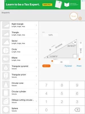
I believe you are bang on. The error is effectively negligible in this alignment. Certainly it's less than induced between sides of a cutter by less-than-perfect tram, for example.
 
Don't you loose a bit of travel at both ends? Either way it wouldn't bother me either.
Yes, I lose a few millimeters at both ends. I've never reached the bottom, and I'm happy losing the 2mm at the top ;-)
 
I have a question for those of us who are much fussier than I am. I see references to cosine errors regarding alignment of scales.

You are a trouble maker! LOL!

But ya, I agree completely regarding cosign error. I'm sorry if anything I said led you to believe I'm concerned about cosine error on my DRO scales. Frankly I don't worry much about it either other than for long distances where it does matter a wee "bit" more - but prolly not anywhere near as much as proportionality. I'm much more concerned about a lot less than a 16th gap variation affecting sensor signal strength and changing the distance reading than I am about cosign error. I'm also concerned about scale proportionality - does an 18" movement display 18.0000 or 18.2467?

Therefore my primary focus adjusting scales to date has been maintaining a constant gap by making sure that the scales are parallel and coaxial to the relative path of the sensor. That said, magnetic scales don't seem to be that sensitive to gap error so maybe even that is a complete and utter waste of my time and effort...... LOL!

The jury is still out on the issue of linearity and proportionality. My unit can be programmed to compensate for it so I suspect the issue is bigger than I would have guessed. We will see.
 
The jury is still out on the issue of linearity and proportionality.
And this is the piece I don't know how to measure. I can pull out my longest gauge block and check over that length, but that's it. So I can adjust for the error over 4", but on an X axis with 36" of travel that doesn't seem particularly useful.
 
And this is the piece I don't know how to measure. I can pull out my longest gauge block and check over that length, but that's it. So I can adjust for the error over 4", but on an X axis with 36" of travel that doesn't seem particularly useful.

You have to promise not to laugh.......

I use a long shaft indicator for distances less than 3 inches, a vernier for distances up to 8 inches and...are you ready...... a laser for longer distances. It's easily accurate enough for my long distance needs.

I wouldn't mind having a few long standards for comparisons though.
It's good that you saw the light!
 
Back
Top