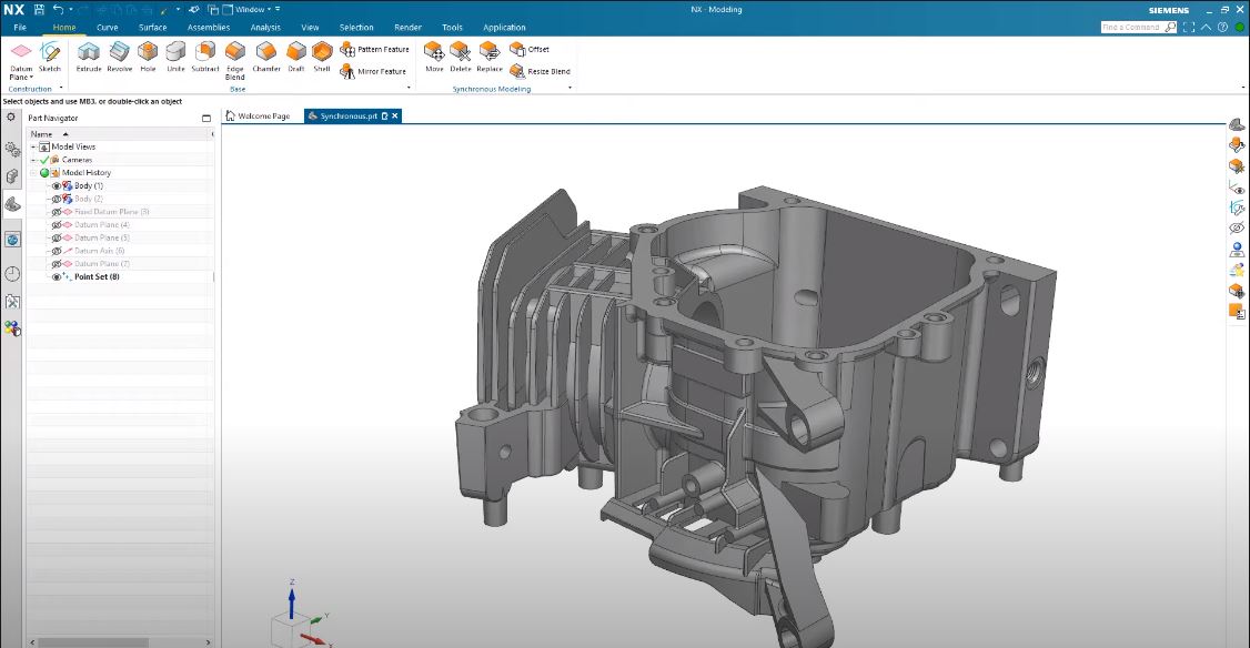
Fusion 3D Trials & Tribulations

PeterT

Ultra Member
Premium Member
I rarely use sketches. start with clay, add, subtract, split offset... etc... then KILL the history .. (kill is my favorite button.. kills the tree)
That sounds more like Catia. You don't start with 2D and morph that into 3D. You start with 3D solids that you shape as appropriate.

Does Fusion have clay and kill functions?

I don't agree with this workflow at all, at least in any CAD environment. Is like burning your blueprints after a part has been manufactured... to accomplish what?.... save valuable real estate within your filing cabinet? What inevitably happens is a minor design change is subsequently required, or a need for a very similar part variant. Or an error is discovered. So with no history available, starting all over again from scratch is somehow more efficient? The memory occupied in the sketches & dimensions is trivial. If you have named & documented your tree elements like you should be doing, you or anyone else should be able to walk through the development steps of that part & see what's going on. Why would you kill that valuable information?

Another red herring is this notion of 'sculpting' from a primitive solid down towards a resultant part vs. 'growing' or 'building up' a part from sketches & their specific 3D operations. One is not better than the other, they are opposite sides of the same coin. Sometimes removing material is the more logical workflow & sometimes its not. The objective is to develop the part in the way that makes the most sense. Some of this thinking stems from earlier 3D programs, or different 3D apps liked mesh modelers (a completely different animal to most conventional 3D modelers). Some of it is self inflicted as people try to relate to programs or explain workflows in practical terms. Some of it possibly stems from CNC machines which have (limited) CAD-like capabilities, but again is different than modelling a part in 3D CAD & importing to a CNC.
 

Susquatch

Ultra Member
Administrator
Moderator
Premium Member
So what exactly is the problem?

Good question..... LMAO!

I solved the original problem described in post #5 and posted the solution to the problem in post #15.

Now I'm just busy learning and asking newbie questions. There is no "problem" anymore. Just questions and learnin.
 

gerritv

Gerrit
Did you click on the triangle? That updates the drawing to new values. Hovering over the icon tells you some guidance.
 

jcdammeyer

John
Premium Member
Yes, that's exactly what I did too.
If I save the assembly file and then reopen it I can then edit the individual parts as ad_prt files. For example I put a 0.25" hole in the top part. The 2D drawing was still open so I had to explicitly tell it to 'Reproject' the views.

1703265546165.png

Then after that it looks like this with the other hole now in the drawing.
1703265493066.png

If Alibre can do this then Fusion certainly can.
 

PeterT

Ultra Member
Premium Member
That sounds more like Catia. You don't start with 2D and morph that into 3D. You start with 3D solids that you shape as appropriate.

Sorry for sidetrack to what is a Fusion post. I've never seen CATIA but always assumed it was $$ industrial strength 3D software, but more or less workflow aligned to alternate parametric apps like Inventor, SolidWorks etc. which are heavily sketch driven. Google is a dangerous thing, but it seems to contradict what you've stated.

1703267122036.png
 

Matt-Aburg

Ultra Member
I don't agree with this workflow at all, at least in any CAD environment. Is like burning your blueprints after a part has been manufactured... to accomplish what?.... save valuable real estate within your filing cabinet? What inevitably happens is a minor design change is subsequently required, or a need for a very similar part variant. Or an error is discovered. So with no history available, starting all over again from scratch is somehow more efficient? The memory occupied in the sketches & dimensions is trivial. If you have named & documented your tree elements like you should be doing, you or anyone else should be able to walk through the development steps of that part & see what's going on. Why would you kill that valuable information?

Another red herring is this notion of 'sculpting' from a primitive solid down towards a resultant part vs. 'growing' or 'building up' a part from sketches & their specific 3D operations. One is not better than the other, they are opposite sides of the same coin. Sometimes removing material is the more logical workflow & sometimes its not. The objective is to develop the part in the way that makes the most sense. Some of this thinking stems from earlier 3D programs, or different 3D apps liked mesh modelers (a completely different animal to most conventional 3D modelers). Some of it is self inflicted as people try to relate to programs or explain workflows in practical terms. Some of it possibly stems from CNC machines which have (limited) CAD-like capabilities, but again is different than modelling a part in 3D CAD & importing to a CNC.

Sorry for sidetrack to what is a Fusion post. I've never seen CATIA but always assumed it was $$ industrial strength 3D software, but more or less workflow aligned to alternate parametric apps like Inventor, SolidWorks etc. which are heavily sketch driven. Google is a dangerous thing, but it seems to contradict what you've stated.

View attachment 41920
Here is the workflow in molds for example.

Customer sends data from different CAD software with no history.
We rename it *.CTM and modify it using synchronous modelling (history kept), all moves on the dumb clay can be changed..
*.CTM part is linked to shrink part, where expansion is added.
shrink part linked to molding part where part is moved to mold position.
molding part is linked to parting part, where core and cavity are split.
parting part sheets are linked to partingline, core part surfaces on layer 27 cavity part surfaces on layer 28
partingline development is done on layer 26. at end of development on layer 26, layer 26 gets parameters removed.
layer 26 is linked to 27 and 28 where they are sewn together to part surfaces
layer 27 partingline and part (sewn) are linked to core block. layer 28 partingline and part (sewn) linked to cavity block.
core and cavity blocks trimmed with linked sheets
all components are then linked and cut from blocks.

This is entirely parametric....


As far as working with dumb clay, I just make a copy and start editing... I do not need to have sketches... never ever use them. @Susquatch

Now I really cannot speak to Fusion as I have not used it that much. I am totally addicted to NX software, which has sketches. I just have never used them once I started working in industry..
 

PeterT

Ultra Member
Premium Member
That makes total sense from a manufacturing perspective. A machinist/CNC operator likely could care less about the history based instructions the part designer developed within CAD model. They really just require the output file/format to feed CAM to make the part. And I can visualize instances where the CAD designer specifically may not want their secret sauce conveyed to 3rd party manufacturing by sending the CAD file. But I suspect for home brew hobby machinists, Mr. CAD & Mr. CAM & Mr. CNC is usually the same guy. Which is why I said deleting history is counterproductive. Actually (and I don't know much about the CAM side) but when I 'save as' .step or .iges or whatever from within CAD it produces a new file specifically for CAM, there is no embedded history that I'm aware of anyways. The original CAD file is none the wiser. Am I missing something?
 

Susquatch

Ultra Member
Administrator
Moderator
Premium Member
Sorry for sidetrack to what is a Fusion post. I've never seen CATIA but always assumed it was $$ industrial strength 3D software, but more or less workflow aligned to alternate parametric apps like Inventor, SolidWorks etc. which are heavily sketch driven. Google is a dangerous thing, but it seems to contradict what you've stated.

View attachment 41920

That's interesting to me Peter. I'm just guessing that sketch support is prolly a new feature to support people coming from other environments who need it. Or maybe it was always there but I never used it. I dunno. I never used sketches. I always started with a solid lump of steel or whatever.

Regardless, I don't really think it would have been difficult to support sketches. As long as that gets you to a solid its all the same orange from there on.

Your assumption is quite correct. Catia is an industrial strength CAE environment used by multi-billion dollar corporations. Its not for hobbiests and I have no interest in going that route. I'm happy with the Fusion Coolaide.

FWIW, I have read that you can even run Catia on a pc now. I have no idea what that would cost. In my day you needed an SGI Workstation or a mainframe to run it. You bought the whole package ready to go.

Just proves that old adage. The only way anything can stay the same is everything changes.
 

Susquatch

Ultra Member
Administrator
Moderator
Premium Member
And I can visualize instances where the CAD designer specifically may not want their secret sauce conveyed to 3rd party manufacturing by sending the CAD file. But I suspect for home brew hobby machinists, Mr. CAD & Mr. CAM & Mr. CNC is usually the same guy. Which is why I said deleting history is counterproductive. Actually (and I don't know much about the CAM side) but when I 'save as' .step or .iges or whatever from within CAD it produces a new file specifically for CAM, there is no embedded history that I'm aware of anyways. The original CAD file is none the wiser. Am I missing something?

There are other Catia based processes that take place in industry too.

You need to design assembly plants and production systems to build and assemble parts.

You need to communicate with suppliers who will make parts that must fit with other parts.

You need to test parts and systems and even whole products for durability, structural integrity, crash worthiness, thermal environmental envelope, stress analysis, fluid dynamics, and you need to be able to assess costs and make cost reductions. The list goes on and on. All of this is done with systems and software integrated with Catia. It's a very powerful environment. Way beyond what we think of with CAD CAM. That's why it's called CAE - Computer Aided Engineering.

What impresses the daylights out of me is that you can do some of that with a much more affordable program like Fusion!

Life is good!
 

Matt-Aburg

Ultra Member
I whipped this off my 3D cellulosic duplicator.

View attachment 41924

The small block is the sliding lock.

View attachment 41925

Fits perfect as drawn.

Some more functional requirements to add, and also some cosmetic features and bevels but so far so good.
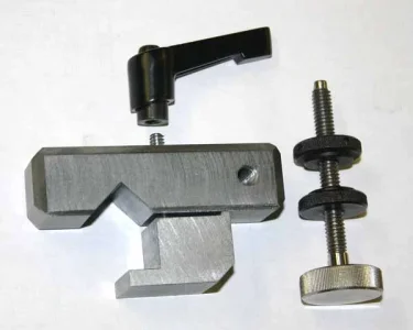
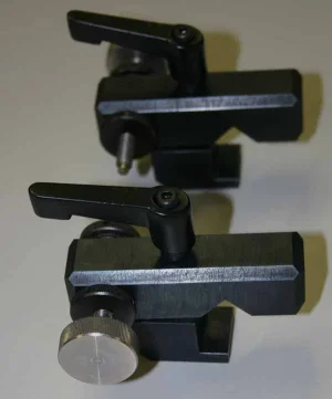
I modified your concept. Note the cap screws on top for easy locking. Just need side screw for adjustability.

1703298377397.png

1703303255304.png
 
Last edited:

Susquatch

Ultra Member
Administrator
Moderator
Premium Member

StevSmar

(Steven)
Premium Member
Here’s my take on a Indicator mounted on the carriage stop that I purchased with my lathe:
IMG_8948.jpeg
There are some recessed magnets holding it on (covered with 1/32 ply to make it easier to remove the chips that get on the magnets)
 

StevSmar

(Steven)
Premium Member
I don't agree with this workflow at all, at least in any CAD environment. Is like burning your blueprints after a part has been manufactured...
The time I “kill the design history” is when I’ve got a complicated assembly and I’ve exceeded the ability of my computer to manage it. Then I’ll start exporting major assemblies as an STL file and import that back in. I still have the original parametric model of course.
 

Susquatch

Ultra Member
Administrator
Moderator
Premium Member
There are some recessed magnets holding it on (covered with 1/32 ply to make it easier to remove the chips that get on the magnets)

I like the idea of a two component design. Keep the stop simple and add the indicator only when needed.
 

StevSmar

(Steven)
Premium Member
Does Fusion have clay and kill functions?
It does have these capabilities.

I had a model where I just couldn’t blend between two bodies in a nice way. I opened the component in the Surface workspace, deleted the faces of the offending bodies and then extruded a surface that made the cuts I needed. Then I turned what was now a surface model back into a solid model...
This is the model that was giving me that grief, with the surfaces I needed to blend:
IMG_2664.jpeg
If you’ve come across something where you think “this would be so easy to do with a file”, then you probably need to use the Surface workspace…

(A bit of background, Fusion doesn’t really make 3D solids, what it does is make surfaces and then the program can “define” a fully enclosed set of surfaces as a solid model. By using the Surface workspace and deleting a surface, I turned the model into a hollowed out shell of zero thickness. I needed to repair the shell and make it fully enclosed again and once that was done Fusion allowed me to turn it back into a solid model)
 

Susquatch

Ultra Member
Administrator
Moderator
Premium Member
If you’ve come across something where you think “this would be so easy to do with a file”, then you probably need to use the Surface workspace…

Thank you Steve, that answers my question.

Could you have done that by starting with two cylinders where the OD of one was a few thou less than the ID of the other, and then add on all the welded brackets?

Just wondering because there is virtually zero chance I'll ever make something so complicated. If I did, I would either machine the whole thing out of a solid block or bolt it together cuz I can't weld.
 
Top