Wood? How much wood would a woodchuck chuck if a woodchuck could chuck wood. And does he use a 3 or 4 jaw chuck...
-
Scam Alert. Members are reminded to NOT send money to buy anything. Don't buy things remote and have it shipped - go get it yourself, pay in person, and take your equipment with you. Scammers have burned people on this forum. Urgency, secrecy, excuses, selling for friend, newish members, FUD, are RED FLAGS. A video conference call is not adequate assurance. Face to face interactions are required. Please report suspicions to the forum admins. Stay Safe - anyone can get scammed.
-
Several Regions have held meetups already, but others are being planned or are evaluating the interest. The Calgary Area Meetup is set for Saturday July 12th at 10am. The signup thread is here! Arbutus has also explored interest in a Fraser Valley meetup but it seems members either missed his thread or had other plans. Let him know if you are interested in a meetup later in the year by posting here! Slowpoke is trying to pull together an Ottawa area meetup later this summer. No date has been selected yet, so let him know if you are interested here! We are not aware of any other meetups being planned this year. If you are interested in doing something in your area, let everyone know and make it happen! Meetups are a great way to make new machining friends and get hands on help in your area. Don’t be shy, sign up and come, or plan your own meetup!
You are using an out of date browser. It may not display this or other websites correctly.
You should upgrade or use an alternative browser.
You should upgrade or use an alternative browser.
Fusion 3D Trials & Tribulations
- Thread starter Susquatch
- Start date
slow-poke
Ultra Member
Okay, I need to make one of these for my BB lathe. It's not obvious to me what actually holds this in place?V4 of the lathe stop... I will look at indicator later as an addon option.. and BTW, Fusion fasteners are GOOD, even though this was imported back into NX.. better than having to download from mcmaster carr
View attachment 41977
Okay, I need to make one of these for my BB lathe. It's not obvious to me what actually holds this in place?
I'm on my way to get a solid gold battery for my row crop tractor. Its really only lead, but the cheapest one I could find was $750. The Deere version is almost 3 grand.
When I get home, I'll post another photo of that. It's basically a sliding block that tightens onto the inside bottom corner of the way. Pockets in the sliding block capture the screw ends, and main block is threaded. Lots of other ways to do it.
Okay, I need to make one of these for my BB lathe. It's not obvious to me what actually holds this in place?
I'm stuck waiting for the battery to be charged so I went down the street to get a pizza.
I added you to a DM Thread on Fusion and my stop. I think there is a Fusion File there.
The stop isn't a high strength accessory. My guess is that you could modify my file for your lathe and print out a working part on your 3D printer that would be every bit as good as my future aluminium stop. I'm so jealous of you guys that can do that.
I plan to add a few more features to my stop that would be easy to do with a printer. But for now wood is my easiest prototyping option.
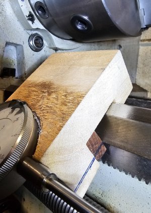
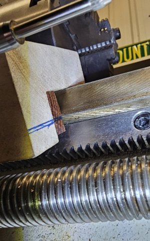
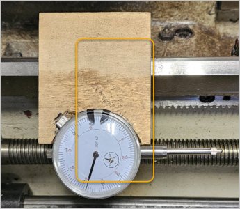
@slow-poke - here are the photos I promised.


The pen lines were just to find the centerline of the sliding block to intersect the bottom of the way.
It's important to know that the way is a 90 degree V with the top ground off. So a 90 degree block rides it perfectly. Also, the line of the bottom of the way is behind the V so the main block is pulled square as the sliding block is tightened.
In the working stop, the sliding block (the dark brown wood) will be a wee bit thinner to ease installation and will have a V relief machined into it to improve the grip on the bottom of the way.
Originally, I was going to include a micrometer thimble, but I see no point given that it would be too easy to damage it. I'd rather just watch the dial gauge.
If you'd design your battery systems like the TESLA you wouldn't have all these problems.

Not quite sure what mounts to what on your design but maybe it could be made with a smaller footprint & still have the same datum surfaces/area plus access to your knurled adjuster?
Some dial mounts use only the dial stem via a hole with a slit (allows rotation reorientation of the dial body). Some integrate the backplate lug if its preferred to keep it on vs the plain back plate. Some seem to use the flat of the backplate on a recess datum and (I guess?) the lug if orientated along the stem axis. Lots of ways to go. One rec is to use a quick acting clamp & keep stick out of anything absolutely minimal around the big spinny thing. It becomes a swarf catcher, finger bumper-inner etc
Some dial mounts use only the dial stem via a hole with a slit (allows rotation reorientation of the dial body). Some integrate the backplate lug if its preferred to keep it on vs the plain back plate. Some seem to use the flat of the backplate on a recess datum and (I guess?) the lug if orientated along the stem axis. Lots of ways to go. One rec is to use a quick acting clamp & keep stick out of anything absolutely minimal around the big spinny thing. It becomes a swarf catcher, finger bumper-inner etc
Attachments
Not quite sure what mounts to what on your design but maybe it could be made with a smaller footprint & still have the same datum surfaces/area plus access to your knurled adjuster?
Good thoughts Peter. I had originally planned a clamp on the stem but the plunge indicators I have all have the back tang mount.
I had also wanted a micrometer hard stop, but that idea is dead because it has zero value.
Less stock is always good.
So the truth is that a smaller stop makes a lot of sense now. Especially if it solves access to the dial adjuster clamp screw. But even on its own, who wouldn't like a smaller stop?
This all said and agreed, I need a bit more functionality for threading so it may well also get bigger! Sometimes we save to spend! LOL!
Thanks Peter!
Well, thanks to inspiration via Susquatch and Blondihacks for the ready made 3D model and 20 minutes of print time in draft mode I have a working prototype that fits my lathe.
I will make a "better" one from aluminum or steel in the near future.
Awesome. It's times like this when I am SOOOO jealous of guys who can run Fusion and have 3D printers.
Couple of comments.
Top of V way needs to be taller to avoid capping out. Make it more of a V-slot so it sits on the way without bottoming out.
The hole for the indicator stem needs to have a clamp built into it somehow. I favour a longer block, a slit, & a through screw.
slow-poke
Ultra Member
From the blondihacks video, she determined the angle is not actually 90 degrees, the plastic deforms, but the metal one will be done correctly. Watching her video I have come to the conclusion that I need want to get a depth micrometer, so if anyone has an extra that they want to sell, please let me know before I go ebay surfing.
At this rate I'm going to need to make another tool chest;-)
I see DavidR8 picked one up a while back, David, do you recall what you paid? Or anyone what is a fair price for good used?
There is a cheap MIC one here in Ottawa on Kijiji, but Shawn wants more than the delivered new price from Amazon.
At this rate I'm going to need to make another tool chest;-)
I see DavidR8 picked one up a while back, David, do you recall what you paid? Or anyone what is a fair price for good used?
There is a cheap MIC one here in Ottawa on Kijiji, but Shawn wants more than the delivered new price from Amazon.
From the blondihacks video, she determined the angle is not actually 90 degrees, the plastic deforms, but the metal one will be done correctly.
Good point. Its been so long since I started this thread, I forgot that many lathes are not 90.
Fortunately, mine is a perfect 90. So I don't need to worry about it. Your mileage may vary.
Regardless, the throat width of the V in your block needs to be less than your lathe so it sits properly and doesn't interfere.
I lucked out and found a barely used 0"-6" Moore and Wright in the case for $60.From the blondihacks video, she determined the angle is not actually 90 degrees, the plastic deforms, but the metal one will be done correctly. Watching her video I have come to the conclusion that Ineedwant to get a depth micrometer, so if anyone has an extra that they want to sell, please let me know before I go ebay surfing.
At this rate I'm going to need to make another tool chest;-)
I see DavidR8 picked one up a while back, David, do you recall what you paid? Or anyone what is a fair price for good used?
There is a cheap MIC one here in Ottawa on Kijiji, but Shawn wants more than the delivered new price from Amazon.
Never, assume anything......
@slow-poke - you do know that virtually every caliper ever made has a perfectly serviceable thousandths depth device built right into it...... It's that long skinny bar that sticks out as the caliper is opened.
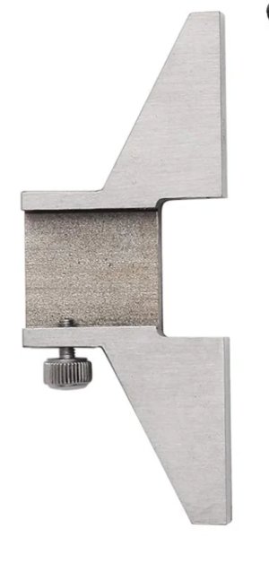
You can even buy (or make) depth stops for them......

I'm not trying to talk you out of getting a depth mic, in fact I have a nice one, but 95% of the time, I use a caliper. The base above is a handy add-on and can prolly be had for $20.
@slow-poke - you do know that virtually every caliper ever made has a perfectly serviceable thousandths depth device built right into it...... It's that long skinny bar that sticks out as the caliper is opened.
You can even buy (or make) depth stops for them......

I'm not trying to talk you out of getting a depth mic, in fact I have a nice one, but 95% of the time, I use a caliper. The base above is a handy add-on and can prolly be had for $20.
slow-poke
Ultra Member
Thanks, yes well aware, however I have convinced myself that I need want a depth micrometer for when I want to know for sure how deep a hole is, and this seems to come up fairly often.
Seems to me as soon as you have a tool that you put off getting, after you get one you wonder how you did without it.
I should get or make the adapter for the caliper, the caliper end is often too narrow and plunging off one side is not very precise.
Seems to me as soon as you have a tool that you put off getting, after you get one you wonder how you did without it.
I should get or make the adapter for the caliper, the caliper end is often too narrow and plunging off one side is not very precise.
I should get or make the adapter for the caliper, the caliper end is often too narrow and plunging off one side is not very precise.
I have two. One for using with calipers in the tool room in the house, and one for the shop. They are good to a thou. I rarely use my depth micrometer.
TorontoBuilder
Sapientia et Doctrina Stabilitas
Well, thanks to inspiration via Susquatch and Blondihacks for the ready made 3D model and 20 minutes of print time in draft mode I have a working prototype that fits my lathe.
I will make a "better" one from aluminum or steel in the near future.
View attachment 54100
View attachment 54093View attachment 54094View attachment 54095
I went another way for my clamping... a fast lever action to be able to reposition the clamp fast. I made it as an end switch to reverse the lathe when threading
I printed the lever and the bearing surface.
I can easily modify to add a indicator holder, instead of the microswitches
Took no time at all to model and print.
Tomc938
Ultra Member
The battery from JD was 3 grand? That sure is dear.I'm on my way to get a solid gold battery for my row crop tractor. Its really only lead, but the cheapest one I could find was $750. The Deere version is almost 3 grand.
When I get home, I'll post another photo of that. It's basically a sliding block that tightens onto the inside bottom corner of the way. Pockets in the sliding block capture the screw ends, and main block is threaded. Lots of other ways to do it.
Make a battery box on a small trailer you can pull behind your tractor and mount a couple of truck batteries on it. For 3 grand you could also add a generator to charge the battery and run a small espresso machine for coffee breaks. And a Laz-E-Boy recliner.
And a beer fridge.
I made it as an end switch to reverse the lathe when threading
I love this. I assume you used a contactor to activate the reverse circuit.
Did you consider just braking? It seems to me that would be both faster and simpler.
Question. My Alibre maintenance expires in a month and they want another $485 to renew my support plan. It would be fine if they added features I could use but the latest effort on their part seems to be on some sort of collaboration software for teams and cloud based file storage.I went another way for my clamping... a fast lever action to be able to reposition the clamp fast. I made it as an end switch to reverse the lathe when threading
View attachment 54209
I printed the lever and the bearing surface.
View attachment 54210
I can easily modify to add a indicator holder, instead of the microswitches
View attachment 54211
Took no time at all to model and print.
Sound familiar? The problem is that many people now can supply projects designed with Fusion360 but they want $685 per year for access after the trial period. So more expensive than Alibre but with Fusion360 one can take the fusion drawing and export as STEP format which can be imported into Alibre.
Now I'd rather see Alibre add the feature to import STEP and STL files but that doesn't look like it's going to happen. And each version saves files in the latest format which isn't compatible with the older versions. So for example when @DavidR8 creates an AlibreAtom drawing I have to use a newer version Rev 28 I think, in order to view it. I've stayed with Rev 25 because it works better with my CAM software.
And there's the problem. There may not be any difference between Alibre 25 or Alibre 28 from a file structure but if the version information is higher the lower versions just won't load it. So it's a blackmail approach to force people to continually upgrade. I can still load Microsoft WORD or EXCEL files from 20 years ago and they did have a save as feature for quite some time.
So what's the approach with Fusion360. Once you stop paying do you lose the ability to look at your old files, edit your old files etc.?

