ER40 collet chuck

Brian H

Super User
@Jswain- yes, and yes it translates to the workpiece

@historicalarms - I am not sure how I would check for consistent gear mesh.

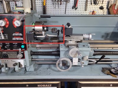
@Bandit ,@PeterT, @RobinHood - I started with the clamshell engaged, turned the chuck to remove backlash, set up the dial indicator (on the tailstock side of the carriage, then turned the chuck the number of threads chosen looking for a 1" movement.
I have a witness mark on the chuck and headstock for a reasonably accurate reference point. I did everything by hand without the lathe even powered up

@Janger -indicator is on a magnetic base. I actually am considering getting another one( one on each side of the carriage) to verify the movement. Having two indicators probably isn't a bad thing anyway. And yes, I confirmed headstock lever is on threading, not powerfeed and yes, half-nut lever is engaged on the apron
 

MrWhoopee

Active Member
Looking forward to your comments on disengaging the half nuts while metric threading on an imperial lathe. I love it. But nobody else tried it. Hoping you are the first!
I have done it on my SB, threading metric in a blind bore (replacement gas cap for a Honda motor clone). It works a treat. Just be sure to re-engage on the first revolution when returning.
 

Jswain

Joe
Is this how your compound is set when threading? And are you advancing the compound to take the cuts?

I mistakenly set mine ~ the same as yours(which was ~60 degrees vs 29) result was the thread was very poor & never cut correctly

Crappy pic but here's mine set somewhat correctly ~29 degrees. Some lathes it will actually show 60 on the scale tho...
 

Attachments

  • IMG_4095.jpeg
    IMG_4095.jpeg
    1.7 MB · Views: 12
  • Screenshot_20240406_092042_Photos.jpg
    Screenshot_20240406_092042_Photos.jpg
    265.6 KB · Views: 12
  • 212993-791a771793aafff7cec166d4052a7c6f.jpg
    212993-791a771793aafff7cec166d4052a7c6f.jpg
    24.3 KB · Views: 12

Brian H

Super User
Is this how your compound is set when threading? And are you advancing the compound to take the cuts?

I mistakenly set mine ~ the same as yours(which was ~60 degrees vs 29) result was the thread was very poor & never cut correctly

Crappy pic but here's mine set somewhat correctly ~29 degrees. Some lathes it will actually show 60 on the scale tho...
Yes, this is how I had it set. I didn't advance the compound when I cut the threads, I just "plunged" in .010/cut.
 

Bandit

Super User
Well, I am sure you are getting very frustrated by now with ideas that are not working. If you are game for
another "idea/ a what the?, try to see the difference/ratio between the spindle and the lead screw. You may want to stop reading now!
Anyway, start at the exposed gear end of the head stock, we will be doing imperial, the 40,86,40 gears. What you want to see is the top gear "B" turn 1 turn, and the bottom gear"D" turn 1 turn. Idlers do not change the ratio when driving and driven gears are same size/tooth count. Now we don't know what the quick change gear box (QGGB) is doing in the primary part or elsewhere rite now, what we want to see is if the lead screw turns 1 turn for 1 turn of the spindle/chuck. Yes, I know, the lead screw is covered, but we need to see it. And we need the quick change in the "B 1" position, 8 threads per inch. So, 1 turn of the chuck = 1 turn of the lead screw, this may not show up as much difference, however 8 turns may show something and the more patience/more turns will show more difference, in multiples of 8 turns of the spindle, if there is any!
The "B" selector is handy as the thread count increases by 1 thread each time the other selector is moved up 1 number, other then the 9.5, set. So you can go to 14 threads, 1 by 1. This also means that the chuck will turn the number of turns selected in the quick change while the lead screw should turn 8 turns (1inch? movement).
I hope I am not putting down what you know and your experience, it is difficult to work though what may lead to an answer step by step, not miss anything and have it lead to a possible solution.
 

Brian H

Super User
Well, I am sure you are getting very frustrated by now with ideas that are not working. If you are game for
another "idea/ a what the?, try to see the difference/ratio between the spindle and the lead screw. You may want to stop reading now!
Anyway, start at the exposed gear end of the head stock, we will be doing imperial, the 40,86,40 gears. What you want to see is the top gear "B" turn 1 turn, and the bottom gear"D" turn 1 turn. Idlers do not change the ratio when driving and driven gears are same size/tooth count. Now we don't know what the quick change gear box (QGGB) is doing in the primary part or elsewhere rite now, what we want to see is if the lead screw turns 1 turn for 1 turn of the spindle/chuck. Yes, I know, the lead screw is covered, but we need to see it. And we need the quick change in the "B 1" position, 8 threads per inch. So, 1 turn of the chuck = 1 turn of the lead screw, this may not show up as much difference, however 8 turns may show something and the more patience/more turns will show more difference, in multiples of 8 turns of the spindle, if there is any!
The "B" selector is handy as the thread count increases by 1 thread each time the other selector is moved up 1 number, other then the 9.5, set. So you can go to 14 threads, 1 by 1. This also means that the chuck will turn the number of turns selected in the quick change while the lead screw should turn 8 turns (1inch? movement).
I hope I am not putting down what you know and your experience, it is difficult to work though what may lead to an answer step by step, not miss anything and have it lead to a possible solution.
I absolutely appreciate the time everyone is taking to walk through this with me. And, just an FYI, I am a "self taught" learn by doing guy (with alot of help from "youTube). I started with a little table top PA mill and 8x11 Chinese lathe about 4-5 years ago. I upgraded to a King PDM-30 mill Nearly 2 years ago and just purchased my 12x 36 King lathe in December. SO, not much in the way of experience at all.

I just tried the 8TPI and here are the results on the lead screw gear with each rotation of the chuck
1 rotation-2 teeth past
2 rotation 5.5 teeth past
3 rotation 7 teeth past
seems consistent but, to me this implies the ratio in the QCGB is incorrect...
 

Darren

Ultra Member
Premium Member
Have you verified that the leadscrew is in fact an imperial leadscrew? 8tpi and 3mm pitch are both common and are pretty close.... Set a caliper at 3" or 4" and verify that its tips line up at the the same spot on the threads.
 

Brian H

Super User
Have you verified that the leadscrew is in fact an imperial leadscrew? 8tpi and 3mm pitch are both common and are pretty close.... Set a caliper at 3" or 4" and verify that its tips line up at the the same spot on the threads.
Yes I just re-checked and from 1"- 5" everything lines up
 

jcdammeyer

John
Premium Member
I found this. Might be helpful although a lot to read through to match the lathe to the calculator.
 

Bandit

Super User
It looks like I caused some confusion. The ratio between the spindle/chuck to the the gear "B", the top gear may not be 1 to 1, and the quick change box will not be a 1 to 1 ratio through it in most or all of the settings. What we want to see is the"B" gear turning 1 turn and the "D" gear turning 1 turn. This will confirm that "B" and "D" are the same tooth count and the compound gearing is not still engaged. If the spindle/chuck turns 1 turn and the "B" gear turns 1 turn, that's good to know, what we want to see is if the spindle turns 1 turn and the lead screw turns 1 turn, when the quick change box is in the 8 threads per inch setting --"B - 1".
The lead screw should always be turning 8 turns for 1 inch of travel of the saddle/carrage if it is a 8 pitch per inch lead screw. What gives the different threads per inch is how many times the spindle turns while the saddle/carrage moves 1 inch, but I am sure you knew that.
 

PeterT

Ultra Member
Premium Member
To post #86 & 87, I was kind of wondering the same thing, but not sure I'm interpreting the gear schematic correctly. If yellow shade is the spindle gear train (various gear combinations possible by levers or knobs). And tan is the leadscrew gear train (various gear combinations), does that leave the 2 gears in red box as the intersecting gears between them? If they were swapped, would that make a different ratio passed onto leadscrew (but still permissible as a factory mistake because gear centers are the same). I haven't had my 2nd coffee so might be barking up the wrong tree.

1712508181078.png
 

RobinHood

Ultra Member
Premium Member
does that leave the 2 gears in red box as the intersecting gears between them?
I believe those compound gears are used for feed reverse.

Looking at the main gear table in the manual, both are 45T/40T (40T/45T) combos meshing with a 45T on the spindle. I would think that it is physically impossible to install them “backwards” because of their size difference.
 

RobinHood

Ultra Member
Premium Member
@Brian H : do you mind doing a little experiment?

1) can you take the 91T/86T combo gear and turn it around 180* on it’s shaft so that the 91T portion is closest to the headstock (opposite to the way you have it in your picture in post #13 above)
2) mesh the 45T ”F” input gear with the 91T section
3) adjust the banjo such that the 86T compound gear meshes with the 60T “G” output gear into the QCGB
4) set your QCGB levers to B-6
5) do a scratch pass into some plastic and measure the pitch: it should be 1.5mm

Your turned-around combo gear should look like this. Please note that the 60T G gear and the 86T compound section should be in mesh (I could not photoshop it properly to show it).

IMG_4096.jpeg

Why do all this?

I have reason to believe that the schematic depiction of the combo gear may be drawn incorrectly (backwards) in both the manual and the diagram stuck to your lathe.
 

Brian H

Super User
@Brian H : do you mind doing a little experiment?

1) can you take the 91T/86T combo gear and turn it around 180* on it’s shaft so that the 91T portion is closest to the headstock (opposite to the way you have it in your picture in post #13 above)
2) mesh the 45T ”F” input gear with the 91T section
3) adjust the banjo such that the 86T compound gear meshes with the 60T “G” output gear into the QCGB
4) set your QCGB levers to B-6
5) do a scratch pass into some plastic and measure the pitch: it should be 1.5mm

Your turned-around combo gear should look like this. Please note that the 60T G gear and the 86T compound section should be in mesh (I could not photoshop it properly to show it).

View attachment 46338

Why do all this?

I have reason to believe that the schematic depiction of the combo gear may be drawn incorrectly (backwards) in both the manual and the diagram stuck to your lathe.
I looked at that when I originally was trying to turn metric threads and the center hub/bearing assembly would have to be pressed in and out of the gear in order to rotate it because there is a spacer that is part of the assembly. I'm presuming they wouldn't have designed it that way
 

Susquatch

Ultra Member
Administrator
Moderator
Premium Member
I looked at that when I originally was trying to turn metric threads

I sure wish we lived closer. I would LOVE to dig into that nasty problem of yours with you. It would be great fun! I know you won't agree for now, but I'm actually jealous of the fun you are having.
 
Top