-
Scam Alert. Members are reminded to NOT send money to buy anything. Don't buy things remote and have it shipped - go get it yourself, pay in person, and take your equipment with you. Scammers have burned people on this forum. Urgency, secrecy, excuses, selling for friend, newish members, FUD, are RED FLAGS. A video conference call is not adequate assurance. Face to face interactions are required. Please report suspicions to the forum admins. Stay Safe - anyone can get scammed.
-
Several Regions have held meetups already, but others are being planned or are evaluating the interest. The Calgary Area Meetup is set for Saturday July 12th at 10am. The signup thread is here! Arbutus has also explored interest in a Fraser Valley meetup but it seems members either missed his thread or had other plans. Let him know if you are interested in a meetup later in the year by posting here! Slowpoke is trying to pull together an Ottawa area meetup later this summer. No date has been selected yet, so let him know if you are interested here! We are not aware of any other meetups being planned this year. If you are interested in doing something in your area, let everyone know and make it happen! Meetups are a great way to make new machining friends and get hands on help in your area. Don’t be shy, sign up and come, or plan your own meetup!
You are using an out of date browser. It may not display this or other websites correctly.
You should upgrade or use an alternative browser.
You should upgrade or use an alternative browser.
DavidR8's shop shenanigans
- Thread starter David
- Start date
Sweet, I'll definitely take it!That's it. I was able to bolt my PF directly to the boss on the table without said bracket.
Cool! Thanks mate, I really appreciate it!Done, I'm going to do a KMS run next week so I'll text you when that is going to happen.
Tom O
Ultra Member
I’m curious do you eat a lot of ginger? When I was on blood thinners and was getting monitored weekly I ate a bag of candied ginger and the next test they told me to stop taking the thinners and any problems go straight to the hospital it took a good week to balance itself out.Thanks Pete, seems you’re stuck with me!
Between my partner and excellent medical care I’m in good hands
Kale (and most leafy green veggies) are high in vitamin K which is the antidote to anticoagulants. I expect that your acquaintance probably raised his clotting factor too high.
If I have to have surgery they will give me a shot of vitamin K so that I don’t bleed out.
")
Interesting, I appreciate that information as I'm more wary of and avoid things that counteract the thinners but wasn't aware of foods that increase their effects.I’m curious do you eat a lot of ginger? When I was on blood thinners and was getting monitored weekly I ate a bag of candied ginger and the next test they told me to stop taking the thinners and any problems go straight to the hospital it took a good week to balance itself out.
We do have candied ginger in the house and I have a piece likely every other day, maybe more often.
I finally felt well enough to venture into the shop so I took the afternoon off.
Made serious progress on the mill power feed.
Originally I planned to mount the feed on the right side of the table. That would have required boring out the ring gear to fit the end of the lead screw.
For reasons unknown to me, the two ends of the lead screw are different diameter. The left side fit the ring gear perfectly. So I revised the plan and decided to put it on the left side of the table.
I also decided to lay the drive horizontally front to back as that gave me more clearance over the base of the mill.
This also allowed me to use the round mounting collar that came with the unit.
(Huge thanks to @YotaBota for donating the regular horizontal mount but it proved unnecessary in the end.)
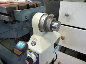
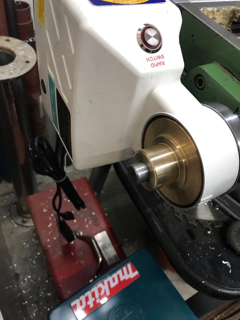
I faced off 1/2” of the collar and then bored it out so it slipped over the snout of the cast iron bracket that bolts onto the table.
(The pic below is a test to make sure it would fit snug on the bracket)
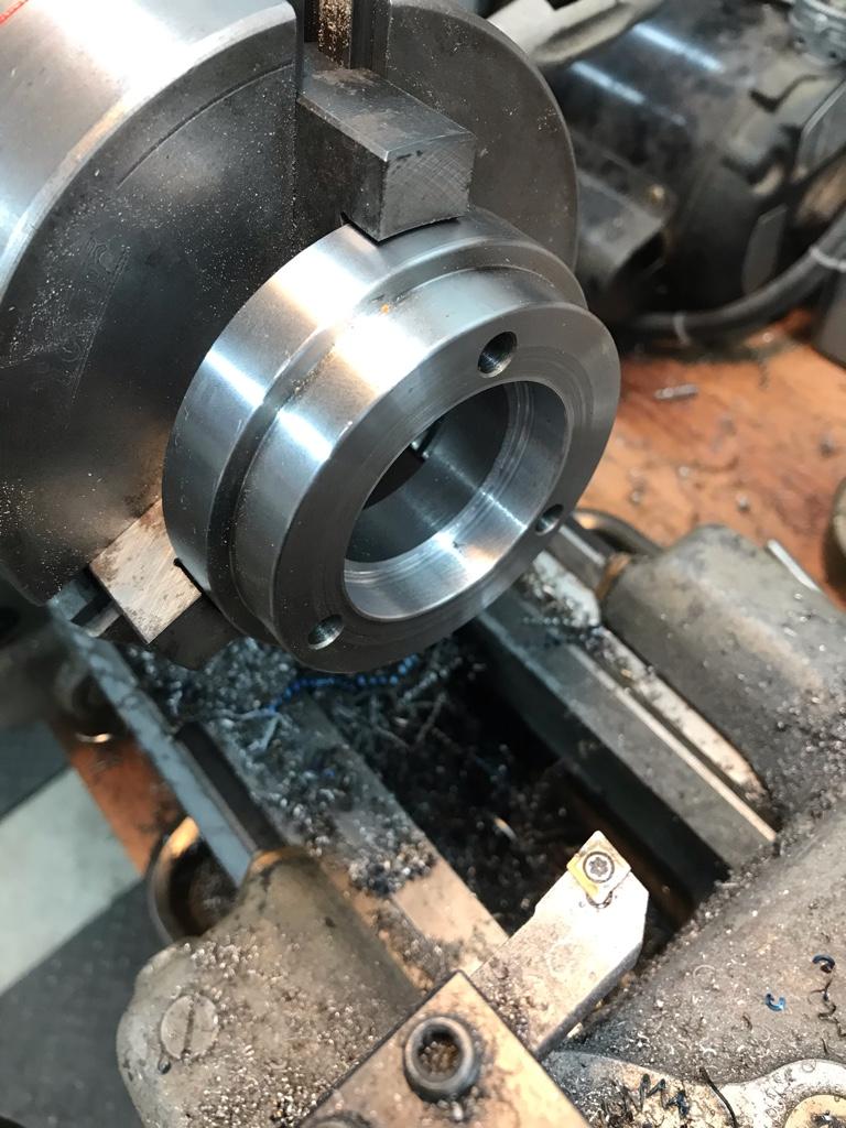
I then positioned the ring so the two of the three mounting holes in the above photo were horizontal on the cast iron bracket.
None of the two tapped holes in the collar matched up with the many holes in the unit but two spots were partially drilled and those worked perfectly.
The gear and shaft is long so I parted it off at the threads.
I still have to figure out how to secure the gear to the lead screw. It has a key way but there isn’t a matching one on the lead screw and don’t have a way to cut one into it. I may cross drill it and use a roll pin but I’d like to be able to adjust the gear mesh.
Another idea is to drill and tap the gear for a set screw or a pair of them on opposite sides. The lead screw is not hardened so I could easily file a flat into it for the screw(s) to land.
Edit: I also need to figure out a cover for the gear so that swarf and chips don't get in there.
One option is to make one from aluminum, the other option is to CAD one up and 3D print it.
Made serious progress on the mill power feed.
Originally I planned to mount the feed on the right side of the table. That would have required boring out the ring gear to fit the end of the lead screw.
For reasons unknown to me, the two ends of the lead screw are different diameter. The left side fit the ring gear perfectly. So I revised the plan and decided to put it on the left side of the table.
I also decided to lay the drive horizontally front to back as that gave me more clearance over the base of the mill.
This also allowed me to use the round mounting collar that came with the unit.
(Huge thanks to @YotaBota for donating the regular horizontal mount but it proved unnecessary in the end.)
I faced off 1/2” of the collar and then bored it out so it slipped over the snout of the cast iron bracket that bolts onto the table.
(The pic below is a test to make sure it would fit snug on the bracket)
I then positioned the ring so the two of the three mounting holes in the above photo were horizontal on the cast iron bracket.
None of the two tapped holes in the collar matched up with the many holes in the unit but two spots were partially drilled and those worked perfectly.
The gear and shaft is long so I parted it off at the threads.
I still have to figure out how to secure the gear to the lead screw. It has a key way but there isn’t a matching one on the lead screw and don’t have a way to cut one into it. I may cross drill it and use a roll pin but I’d like to be able to adjust the gear mesh.
Another idea is to drill and tap the gear for a set screw or a pair of them on opposite sides. The lead screw is not hardened so I could easily file a flat into it for the screw(s) to land.
Edit: I also need to figure out a cover for the gear so that swarf and chips don't get in there.
One option is to make one from aluminum, the other option is to CAD one up and 3D print it.
Last edited:
Cross drilling won't be my first choice because, as you stated, there is no way for any future adjustment. Plus the fact that you weaken the shaft at that point.
You may have been premature in cutting the gear shaft, how are you going to secure the gear at the required clearance?
Do you know any one with a milling machine that might let you use it to cut the keyway in your lead screw? wink wink nudge nudge.
You may have been premature in cutting the gear shaft, how are you going to secure the gear at the required clearance?
Do you know any one with a milling machine that might let you use it to cut the keyway in your lead screw? wink wink nudge nudge.
Cross drilling won't be my first choice because, as you stated, there is no way for any future adjustment. Plus the fact that you weaken the shaft at that point.
You may have been premature in cutting the gear shaft, how are you going to secure the gear at the required clearance?
Do you know any one with a milling machine that might let you use it to cut the keyway in your lead screw? wink wink nudge nudge.
Sorry I don’t think I was really clear.
I haven’t cut anything except the long end of the brass gear. There’s still plenty of material to secure the gear to the shaft.
The key way is tiny, probably only a 2mm wide by 1cm long. I’ve had to search for the key once already when it went skittering off the bench.
DPittman
Ultra Member
Good to hear your getting back at it.I finally felt well enough to venture into the shop so I took the afternoon off.
Made serious progress on the mill power feed.
Originally I planned to mount the feed on the right side of the table. That would have required boring out the ring gear to fit the end of the lead screw.
For reasons unknown to me, the two ends of the lead screw are different diameter. The left side fit the ring gear perfectly. So I revised the plan and decided to put it on the left side of the table.
I also decided to lay the drive horizontally front to back as that gave me more clearance over the base of the mill.
This also allowed me to use the round mounting collar that came with the unit.
(Huge thanks to @YotaBota for donating the regular horizontal mount but it proved unnecessary in the end.)
I faced off 1/2” of the collar and then bored it out so it slipped over the snout of the cast iron bracket that bolts onto the table.
(The pic below is a test to make sure it would fit snug on the bracket)
I then positioned the ring so the two of the three mounting holes in the above photo were horizontal on the cast iron bracket.
None of the two tapped holes in the collar matched up with the many holes in the unit but two spots were partially drilled and those worked perfectly.
The gear and shaft is long so I parted it off at the threads.
I still have to figure out how to secure the gear to the lead screw. It has a key way but there isn’t a matching one on the lead screw and don’t have a way to cut one into it. I may cross drill it and use a roll pin but I’d like to be able to adjust the gear mesh.
Another idea is to drill and tap the gear for a set screw or a pair of them on opposite sides. The lead screw is not hardened so I could easily file a flat into it for the screw(s) to land.
Edit: I also need to figure out a cover for the gear so that swarf and chips don't get in there.
One option is to make one from aluminum, the other option is to CAD one up and 3D print it.
Good to hear your getting back at it.
Thanks! It felt good to make some chips.
Even if one of them landed on my nose and burnt me!
I finally felt well enough to venture into the shop so I took the afternoon off.
Made serious progress on the mill power feed.
Originally I planned to mount the feed on the right side of the table. That would have required boring out the ring gear to fit the end of the lead screw.
For reasons unknown to me, the two ends of the lead screw are different diameter. The left side fit the ring gear perfectly. So I revised the plan and decided to put it on the left side of the table.
I also decided to lay the drive horizontally front to back as that gave me more clearance over the base of the mill.
This also allowed me to use the round mounting collar that came with the unit.
(Huge thanks to @YotaBota for donating the regular horizontal mount but it proved unnecessary in the end.)
I faced off 1/2” of the collar and then bored it out so it slipped over the snout of the cast iron bracket that bolts onto the table.
(The pic below is a test to make sure it would fit snug on the bracket)
I then positioned the ring so the two of the three mounting holes in the above photo were horizontal on the cast iron bracket.
None of the two tapped holes in the collar matched up with the many holes in the unit but two spots were partially drilled and those worked perfectly.
The gear and shaft is long so I parted it off at the threads.
I still have to figure out how to secure the gear to the lead screw. It has a key way but there isn’t a matching one on the lead screw and don’t have a way to cut one into it. I may cross drill it and use a roll pin but I’d like to be able to adjust the gear mesh.
Another idea is to drill and tap the gear for a set screw or a pair of them on opposite sides. The lead screw is not hardened so I could easily file a flat into it for the screw(s) to land.
Edit: I also need to figure out a cover for the gear so that swarf and chips don't get in there.
One option is to make one from aluminum, the other option is to CAD one up and 3D print it.
I've been looking at this over and over again, and just don't get the arrangement?
I assume the piece you parted off threads into the gear that meshes with the PF gear?
Why would they have that sleeve in the first place?
I don’t know what the piece I parted off is for when the unit is used on the Y-axis of a Bridgeport style mill.I've been looking at this over and over again, and just don't get the arrangement?
I assume the piece you parted off threads into the gear that meshes with the PF gear?
Why would they have that sleeve in the first place?
I saw @YotaBota mill but I didn’t notice exactly how it was arranged.
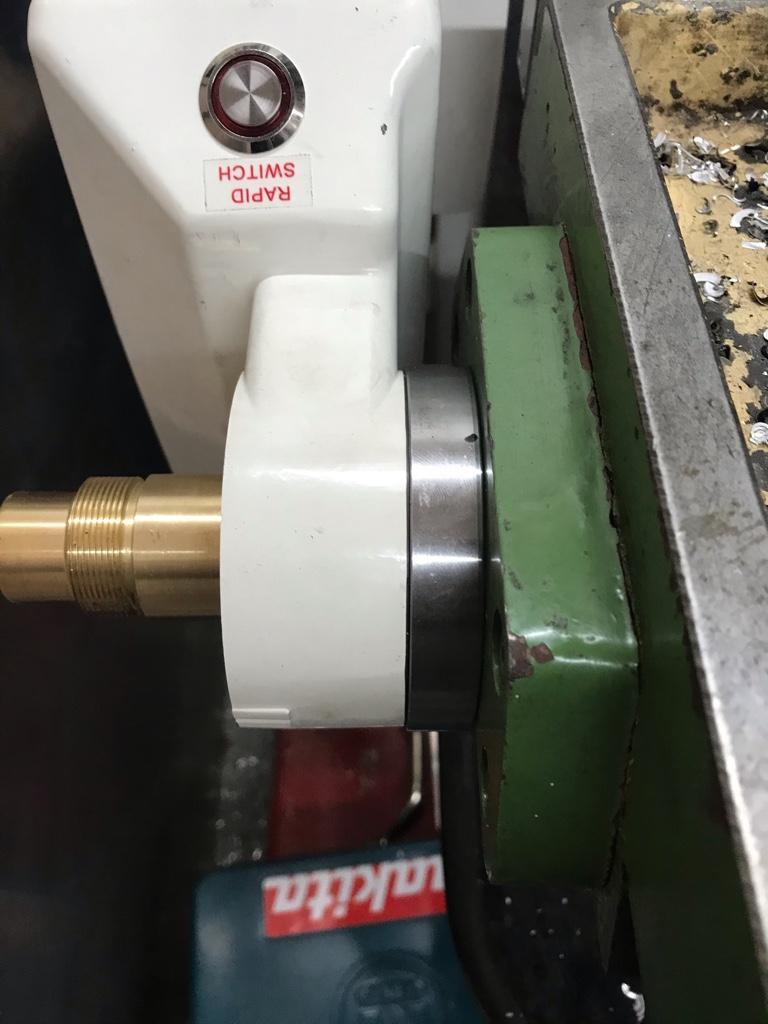
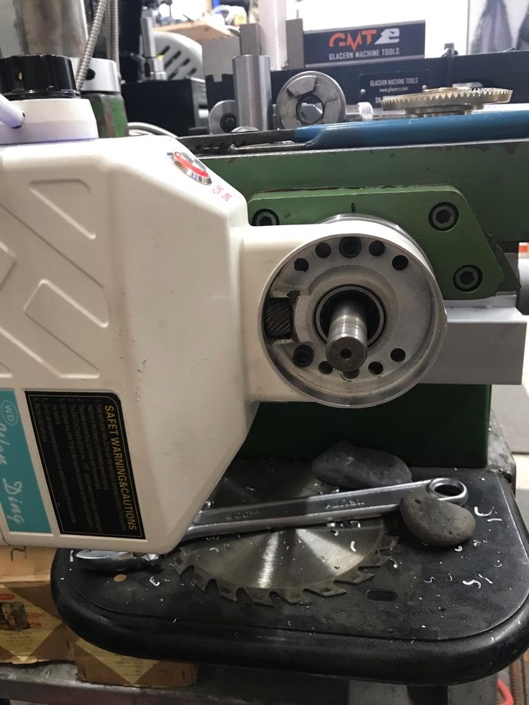
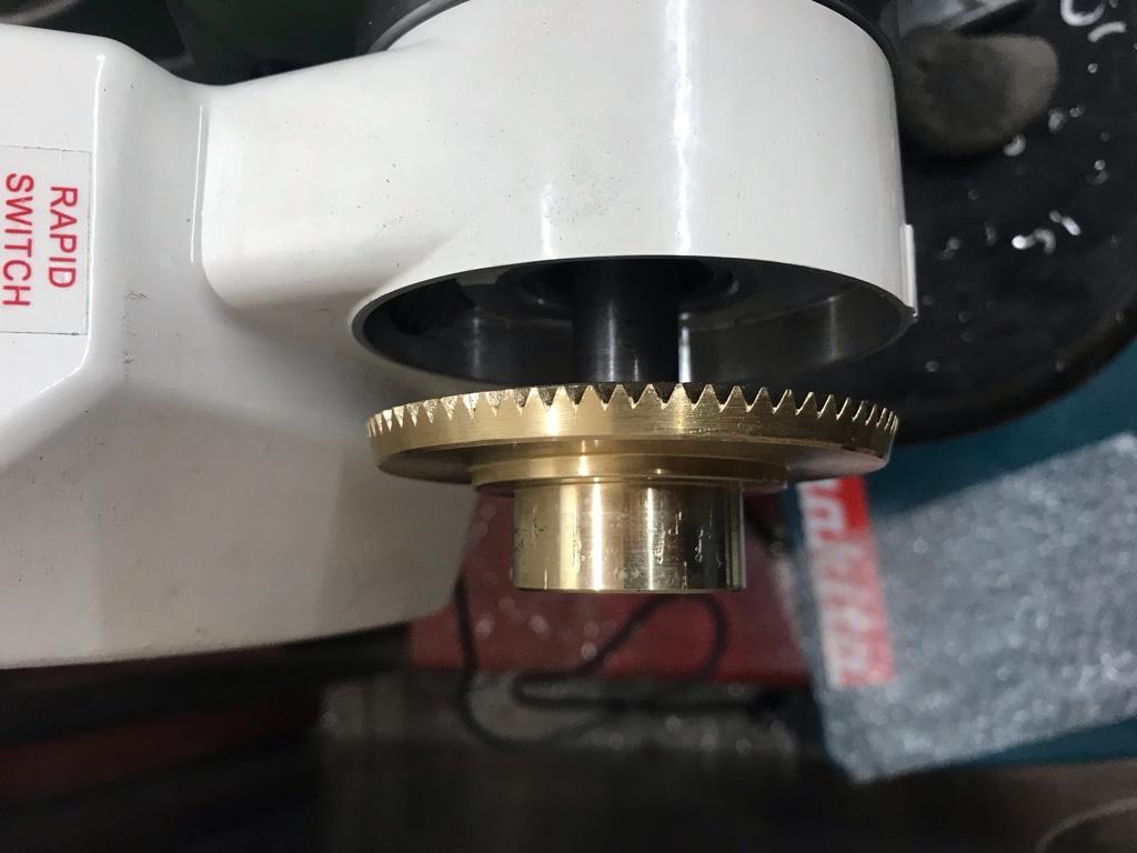
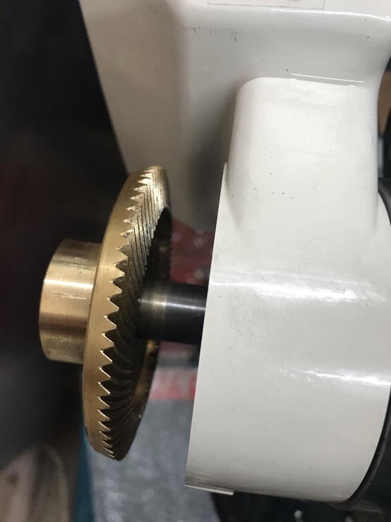
Here’s a couple of pics that may help.
This is the unit mounted without the ring gear in place. The pinion gear is to the left of the lead screw.
There is also a bushing slips over the shaft and runs on a needle bearing in the opening. It’s the silver ring that’s visible around the end of the lead screw.
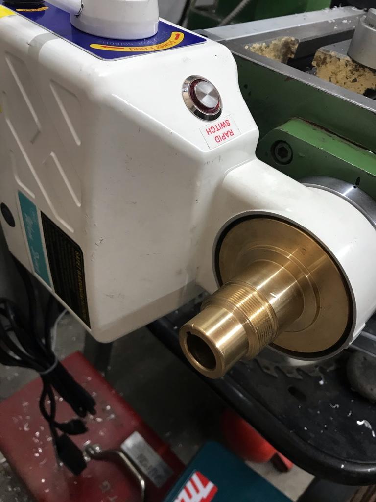
Here is the ring gear partiality on the end of the lead screw.
David I see a threaded hole in the end of the shaft I assume fastened the original crank handle. How is torque transfered from the handle to the shaft? Is there a key? Does the handle slide over the OD of the shaft like a Bridgeport style machine? I'm thinking that you might use a collar and selective shims that slip over the shaft to force the brass gear in mesh with the motor pinion and allow adjustment of backlash. All of this stuff to be held in place by the bolt that fastens crank handle. Then perhaps an axial drive pin or 2 through the handle into the end of the brass gear to transfer torque?
On my mill (6x26 knee) the part your parted off is for the dual spacer which has the graduations on it.
Sent from my iPhone using Tapatalk
Sent from my iPhone using Tapatalk
David I see a threaded hole in the end of the shaft I assume fastened the original crank handle. How is torque transfered from the handle to the shaft? Is there a key? Does the handle slide over the OD of the shaft like a Bridgeport style machine? I'm thinking that you might use a collar and selective shims that slip over the shaft to force the brass gear in mesh with the motor pinion and allow adjustment of backlash. All of this stuff to be held in place by the bolt that fastens crank handle. Then perhaps an axial drive pin or 2 through the handle into the end of the brass gear to transfer torque?
You know I never noticed that that hole was so deep, I always thought it was just a centre drill for a live centre when the lead screw was made.
I don't believe it's tapped though.
The handle is attached with a set screw that bears on the shaft. It has a dog style connection that connects a round collar which is pinned to the shaft.
When the handle and collar are in place there's about .25" of shaft sticking out of the handle.
When the brass gear is snugged up to the pinion gear, there is about .75" of shaft sticking out past the brass part. I might try to see if I can make a thinner version of the round collar and see if I can put the handle back on. I'm not sure I'll have enough shaft length though. I suppose I could just put the handle back on and call it good.
Where did the threaded brass piece in the first image disappear to in the second image?
That's what I parted off.Where did the threaded brass piece in the first image disappear to in the second image?
In the first pic, there's a groove just past the threads. That seemed a logical spot to lop off the excess. I've since parted off an additional .25" or so to make more room on the shaft for another locking collar, or maybe the handle.