• Spring 2024 meetup in Calgary - date Saturday, April 20/2024. discussion Please RSVP Here to confirm and get your invitation and the location details. RSVP NOW so organizers can plan to get sufficient food etc. It's Tomorrow Saturday! you can still RSVP until I stop checking my phone tomorrow More info and agenda
  • We are having email/registration problems again. Diagnosis is underway. New users sorry if you are having trouble getting registered. We are exploring different options to get registered. Contact the forum via another member or on facebook if you're stuck. Update -> we think it is fixed. Let us know if not.
  • Spring meet up in Ontario, April 6/2024. NEW LOCATION See Post #31 Discussion AND THE NEW LOCATION

CT 043 issues ..... Repairs - Completed !!

Darren

Ultra Member
Premium Member
The machine is plugged into a wall outlet with a breaker, which can act act a switch. So, a bypass test can be performed by moving the wires from the input of the contactor to the output side, like a binding post.

Years ago, i got screwed by a bad relay. I swapped a 5.0 Ford into a 65 Falcon. The main relay failed during the swap. It got knocked around a bit.....but it tested 0 Ohms (good, right?), and passed enough current to light up a test light. It would not pass enough current to power up the ECM though. Made me look like an idiot for several hours while several of my customer's friends were there for the big moment. It wa looking grim when i couldn't get er to bark up, but after thinking a bit, I did a quick bypass test and the engine lit right up and i looked like a hero LOL
 

Darren

Ultra Member
Premium Member
I prefer a continuity test for this... and it is very unlikely that a contacts that pass a continuity test will not pass enough current at 30v to energize a coil. The pickup voltage is far less than that IIRC

We've established that the control side is working. I'm talking about line voltage side. Sorry about the confusion
 

PeterT

Ultra Member
Premium Member
Not sure if your lathe is similar but I'll volunteer my 14x40 story FWIW. It was similarly fussy on the FWD/REV lever. I'm no so sure it wear induced or never quite set up right to begin with. When I examine the detent holes the plunger ball goes into, I think it was drilled by the same chimp that hand drilled the other holes. It look eyeballed, not engineered. Now why they have a gronk size lever handle & heavy casting & meaty bar & thick cam... all to actuate a lightly spring contact switched is beyond me. But I digress. As I was futzing around I remember I lost contact on one of the switches & the other was going just out of detente. . Back to the drawing board. There was a bit of play in the detent, a bit in the cam, a bit in how the contact switch was mounted. Some fiddling around & it functions again. Anyhoo, reason I mention is maybe if its checking out on the bench but not in-situ on the lathe has something to do with setup?

I did manage to remove the rod and linkage / lever mechanism that controls the forward / reverse and make a modification that makes it more difficult to accidentally slam it from forward to reverse. There's a notch machined into the support bracket which bolts to the apron , I machined the notch in the part which rotates to make a ramp so the lever is engaged more solidly when positioned , there is a spring to hold it but the notch , combined with a bit of physical wear was making the lever a bit sloppy and not very precise , it's solid now , I like it.
 

Attachments

  • IMG_6350_edited-1.jpg
    IMG_6350_edited-1.jpg
    45.3 KB · Views: 4

Gearhead88

Super User
Not sure if your lathe is similar but I'll volunteer my 14x40 story FWIW. It was similarly fussy on the FWD/REV lever. I'm no so sure it wear induced or never quite set up right to begin with. When I examine the detent holes the plunger ball goes into, I think it was drilled by the same chimp that hand drilled the other holes. It look eyeballed, not engineered. Now why they have a gronk size lever handle & heavy casting & meaty bar & thick cam... all to actuate a lightly spring contact switched is beyond me. But I digress. As I was futzing around I remember I lost contact on one of the switches & the other was going just out of detente. . Back to the drawing board. There was a bit of play in the detent, a bit in the cam, a bit in how the contact switch was mounted. Some fiddling around & it functions again. Anyhoo, reason I mention is maybe if its checking out on the bench but not in-situ on the lathe has something to do with setup?

I did manage to remove the rod and linkage / lever mechanism that controls the forward / reverse and make a modification that makes it more difficult to accidentally slam it from forward to reverse. There's a notch machined into the support bracket which bolts to the apron , I machined the notch in the part which rotates to make a ramp so the lever is engaged more solidly when positioned , there is a spring to hold it but the notch , combined with a bit of physical wear was making the lever a bit sloppy and not very precise , it's solid now , I like it.
I made sure , with my meter after putting the switches back up in their hiding place to operate them several times while watching my ohmmeter .
I gotta say , the switches and cams are in a really bad spot on this one , hidden behind the quick change gearbox casting , they couldn't have made access any more difficult if they tried .
The picture you posted , I only wish it was a nice as that.
 

Darren

Ultra Member
Premium Member
A 5.0 what? I had a 61 Falcon with a 6 cylinder as my first car LOL.. Had no floor boards left under the driver's side. I fiber glassed that in. That thing would change lanes by itself on the hwy when a semi passed you:oops:
a 90ish 5.0 5spd into a 65 Falcon, owner did the mechanical, I wired it
 

RobinHood

Ultra Member
Premium Member
I’ve been sitting on the sidelines of this thread without commenting as lots of good help/advice has been given already.

One thing that I have learned the hard way: never assume anything. Just because a relay works on the bench does not mean that it is good. The coil could test fine, but could be too weak when the relay is installed in a different orientation. Also, the fastening mechanism can distort the body and prevent proper function.

So, here is what I do with them (the quality ones that can be disassembled; the others just get binned): take the whole thing apart. Clean thoroughly, clean all contacts to remove any pitting and make sure the surfaces mate properly. Adjust if required. Check all springs. Reassemble. Power the coil. Make sure the contacts close. Now tap the relay body to make sure the contacts stay closed. If you get buzzing, the coil is bad. Replace the coil.

This is the best way that I have found to make sure there are no surprises with used relays.
 

Susquatch

Ultra Member
Administrator
Moderator
Premium Member
Switch testing can be looked at the same as contactor testing. They both have contacts which are usually the mode of failure. They can be bypassed with jumpers . If it works, theres your problem.

Ive tried to just read and insert only the odd suggestion or comment lest @Gearhead88 get input overload. I confess that I'd be overloaded if I were him.

But this suggestion of yours is solid gold in my opinion. In my 50+ years of diagnosing and repairing electrical equipment, I have come to conclude that about 95% of the failures are the result of connection problems. My favorite advice to people diagnosing electrical devices is always "Connections, connections, connections - check the connections." I would be willing to bet I already said that here earlier. But maybe not. There are a lot of very capable people already trying to help.

As you suggest, one of the easiest and most convenient ways to check a connection is with a jumper wire and/or continuity tester.

This is also a convenient place to add an observation. I think @Gearhead88's approach to this is admirable - albeit painfully slow. He doesn't just want to do what he is told. He wants to understand it first so he can learn something in the process. I happen to admire that trait because I can relate to it. I am a very firm believer in that old saying. "Give a man a fish and you feed him for a day - teach him to fish and you feed him for a lifetime".

Switches, contactors, relays, wiring bulkheads, jumpers and screws etc are all connectors. When the smoke clears, I'll happily provide beer for everyone if it turns out that this problem wasn't a connector. Oh WTF, the beer is all on me regardless.
 

Susquatch

Ultra Member
Administrator
Moderator
Premium Member
I have seen it hundreds of times in my trade.

Me too.

A pitted contact can test just fine with a continuity tester but as soon as the current starts to flow, the low resistance in the pitted contact causes heat to build and suddenly it doesn't flow current anymore. I agree with @RobinHood. It's easy to check and faster to clean them than replace them. That said, they usually pit for a reason and sometimes it's better to replace them.
 
Last edited:

combustable herbage

Ultra Member
Premium Member

Susquatch

Ultra Member
Administrator
Moderator
Premium Member
I prefer a continuity test for this... and it is very unlikely that a contacts that pass a continuity test will not pass enough current at 30v to energize a coil. The pickup voltage is far less than that IIRC

I usually prefer a jumper. I'm not really fond of those cheap bulb type continuity testers. Based on most of what you say, I'll bet you don't mean that kind either. You probably mean an ohmeter. An ohmeter is infinitely better because it will give you much more than a go-no-go evaluation. It will give you a qualitative test of the connection quality. That said, a jumper will test the circuit under load which is better still.

You are of course correct - as I said earlier I believe 95% of such problems are connections and I further believe that 95% of those connection problems can be found with an ohmeter. I don't even own one of those bulb/beep testers anymore.
 

combustable herbage

Ultra Member
Premium Member
Me too.

A pitted contact can test just fine with a continuity tester but as soon as the current starts to flow, the low resistance in the pitted contact causes heat to build and suddenly it doesn't flow current anymore. I agree with @RobinHood. It's easy to check and faster to clean them than replace them. That said, they usually pit for a reason and sometimes it's better to replace them.
Its a snowball effect over time corrosion builds up less surface area for the current to flow, more flow throw the existing good mating surfaces causing more heat causing arcing and pitting causing less surface area again until eventually they just melt away.
We now know the start capacitor is bad so as it was going it could cause higher current draw on start up causing more heat through the contactors accelerating this effect so Gearhead having the contactors soon will give him the option to change one or change all.
I agree with you that wiring is a major cause of problems but having been on both the reporting side and now being involved in some root cause analysis sometimes wiring gets the blame when its really someone not wanting to admit to a simpler problem or made it up to cover something else or when they really didn't find the problem or it went away or even computer glitches sometimes its a catch all for problems. .
When I started out I fixed my parents tv it was the first tv I ever worked on it would get a white line sometimes so I had gotten schematics, meter scope everything ready took it apart flipped it upside down looked at the board, saw 4 or 5 broken solder connections on the board for the vertical which I had looked at earlier in the schematic. It was fixed in the time it took to heat up the soldering iron still works today 35 years later, I was happy it was fixed but my mind was very disappointed I thought the problem is just a connection that's it? no metering no analyzing no scoping that's the fun part and I am still disappointed when its just a broken wire or a bad connection, rather than something I changed after troubleshooting especially if its tough. But it didn't take long to realize that these "connections" where going to make me money especially when others failed ahead of you.
Think of all those great projects Gearheads gonna do once he gets through this blip with this lathe he'll have another 20 or 40 more years out of it.
 

Susquatch

Ultra Member
Administrator
Moderator
Premium Member
Its a snowball effect over time corrosion builds up less surface area for the current to flow, more flow throw the existing good mating surfaces causing more heat causing arcing and pitting causing less surface area again until eventually they just melt away.
We now know the start capacitor is bad so as it was going it could cause higher current draw on start up causing more heat through the contactors accelerating this effect so Gearhead having the contactors soon will give him the option to change one or change all.
I agree with you that wiring is a major cause of problems but having been on both the reporting side and now being involved in some root cause analysis sometimes wiring gets the blame when its really someone not wanting to admit to a simpler problem or made it up to cover something else or when they really didn't find the problem or it went away or even computer glitches sometimes its a catch all for problems. .
When I started out I fixed my parents tv it was the first tv I ever worked on it would get a white line sometimes so I had gotten schematics, meter scope everything ready took it apart flipped it upside down looked at the board, saw 4 or 5 broken solder connections on the board for the vertical which I had looked at earlier in the schematic. It was fixed in the time it took to heat up the soldering iron still works today 35 years later, I was happy it was fixed but my mind was very disappointed I thought the problem is just a connection that's it? no metering no analyzing no scoping that's the fun part and I am still disappointed when its just a broken wire or a bad connection, rather than something I changed after troubleshooting especially if its tough. But it didn't take long to realize that these "connections" where going to make me money especially when others failed ahead of you.
Think of all those great projects Gearheads gonna do once he gets through this blip with this lathe he'll have another 20 or 40 more years out of it.

Ya, it is amazing isn't it!

For a big chunk of the early part of my career I did warranty parts analysis and designed and built test equipment to do repair analysis and diagnostics in automobiles. Remember those giant diagnostic testers the car dealers and auto repair shops had? I prolly designed half of them or at least developed the logic and circuitry they used internally.

They were all crap!

Why crap? Because stupid me assumed the problem was always a complicated part. After all, the mechanics would never overlook a simple problem! Right! Of course they did. They are paid to fix it fast so on goes the analyzer. Usually the problem isn't complicated. Usually it's a basic part or..... a connection.

In fairness, those analysers did do a fairly decent job of testing numerous components and systems all at once. They were great for tune-ups. And they absolutely did convince the customer that they were getting their money's worth at the shops that used one...... Lol!

So I'll add to my "connections connections connections - check the connections" advice. Let's call that advice #1.

Advice #2 would be: "If you don't know how it works, don't assume that what you don't understand is what is broken."

If I had a nickel for every computer, electronic control, microcontroller, black box, and gizmo that got replaced just because somebody didn't know how it worked, I'd be a billionaire today.

And while Im at it, advice #3 would be: "Be very wary of anecdotal evidence." Everybody and their mother has a story to tell about what was wrong with their dads car. So that's obviously what is wrong with mine too. Ya, some problems do tend to be common problems. And if it looks like an oil leak, it's probably an oil leak. But it's still good to be very wary of anecdotal evidence because we are all humans - we survived because we learned to run when something growls in the bushes. He who hesitates dies. So we are quick to blame whatever anecdote shows up first.

Let me conclude by observing that you have/had a great job if you do a lot of forensic root cause work. It's a very rewarding occupation. There are others on this forum that share that joy with us. Perhaps it is connected somehow to the joy of machining and finding that beautiful part that was hiding in that useless chuck of metal.....
 

PeterT

Ultra Member
Premium Member
Nobody commented on his capacitors. What do you guys make of the range? I re-arranged but kept his titles. Just confirming you have 3 of each now? The old motor start cap is obviously oddball. Was that replicated on another measurement or it is what it is? How does one analyze this? Value should lie within a certain tolerance I assume? is there a +/- stated on the capacitors or some replacement catalog data? Did you discharge them all like that video showed?
 

Attachments

  • SNAG-2022-02-05 9.15.50 AM.jpg
    SNAG-2022-02-05 9.15.50 AM.jpg
    34.7 KB · Views: 3

Gearhead88

Super User
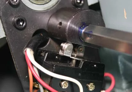
A couple of weeks ago I tried taking one of my contactors apart to get a look inside and stopped part way through , at that point I realized that further disassembly put the part at risk of being damaged or destroyed. These dinky little parts are throw away , non serviceable items , now , getting them is another entirely different challenge as I've discovered. I have no idea when I will be getting the set I ordered on the 28th of January , from what I am seeing on my ebay purchase history page is , the seller is away until Feb 7 , so when he sobers up and gets back to the office to fill all the orders placed over the two weeks he had off , that puts my delivery date well into March. The fact that Busy Bee has no parts sends a clear message as to where they stand on the customer service side , piss poor !!!

I should respond to the comment about how long this is taking.

I have lots of other things going on that eat up time , there's no doubt , my participation on this forum burns lots of it , when I sit down at my computer , the first thing I usually do is look at this forum . I feel welcome here , it's a great group of people and I'll be paying up to get a premium membership .

Other stuff I have going on , is often prioritized above the ongoing lathe issue , even though the end is near and a solution might be soon . I work on it when I have time and If I am not feeling up to it I do other things ...............

Like this ...................

I Started on this project last month , there has been a great deal of progress so far and yesterday I got the remaining parts needed to finish it.
GVIO6392.JPG
This one is a 1978 74 cubic inch Shovelhead
The cylinders have been painted , bored & honed to size , rings fit .
The rods are almost done , the bores on the big end have been honed straight again , they're round and honed to the the target dimension to accept oversized rollers .
I need to press in the bushings on the small end and hone those to the correct clearance and then I will be weighing some of the parts , both rotating & reciprocating , doing some math and then balancing the flywheels , it's labour intensive but worth it .
I have the crank cases cleaned , threads chased , mating surfaces prepped , the roller bearing main on the right side has been lapped to a custom fit with oversize rollers.
The crankshaft , once it has been balanced needs to be assembled , trued and installed into the crankcases.
The heads have been cleaned , bead blasted , the valves have been ground as well as the seats , ground to three angles , those need to be assembled with the new springs I just got yesterday .
Then there's the oil pump cam chest and top end that needs to be assembled . The rocker arms have had new bushings pressed in and sized .
All of this is done lovingly , each piece massaged , hand fit and measured to ensure it is right .


The lathe ?

pppppfffffff , I might work on it a bit today , or tomorrow or monday , tuesday its back to work .

Oh I almost forgot I have nine month old 100 lb puppy thats very mischievious and full of energy , she's my chief of security , in training .

So you see , I do have a full dance card
 
Last edited:

Gearhead88

Super User
Nobody commented on his capacitors. What do you guys make of the range? I re-arranged but kept his titles. Just confirming you have 3 of each now? The old motor start cap is obviously oddball. Was that replicated on another measurement or it is what it is? How does one analyze this? Value should lie within a certain tolerance I assume? is there a +/- stated on the capacitors or some replacement catalog data? Did you discharge them all like that video showed?
The old motor - The start capacitor measured way low , it's in the garbage now , I installed a new one I got on Amazon , the run capacitor measured up ok but had some cracked insulation on the wires , that's in the trash too , I bought both when I placed the order .
The windings had 1 ohm of resistance measured across U1 & U2.
I had the old motor apart to look for evidence of damage or burned wires etc.

Something that bugs me about these motors is the terminals , knowing almost nothing about AC electric motors , what messes with me is ,the old motor has six terminals & the new one has four.

The new motor - the capacitors measured up to be very close to the same as what is printed on the outside of them so I'm calling them good .
The windings also appeared to be good .
 
Last edited:
Top