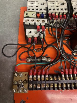
That's why I had suggested running just on the 24volts safe , you can operate it on off rev/fwd, bypass any external switches to make a simpler circuit then see what's happening and not happening, sometimes proving what works leads you to the problem rather than just blasting components with the shotgun till you find the right one. Good luck Gearhead!The only point i'm trying to make is that regardless of the wiring diagram, the machine can easily be diagnosed. Theres a physical diagram right there. There's no electronics here, just some simple components to test, follow the power from the cord to the motor. Verify that whichever motor is installed actually works. Hook power direct. Once verified, it can be used as a load for all further testing.
-
Scam Alert. Members are reminded to NOT send money to buy anything. Don't buy things remote and have it shipped - go get it yourself, pay in person, and take your equipment with you. Scammers have burned people on this forum. Urgency, secrecy, excuses, selling for friend, newish members, FUD, are RED FLAGS. A video conference call is not adequate assurance. Face to face interactions are required. Please report suspicions to the forum admins. Stay Safe - anyone can get scammed.
-
Several Regions have held meetups already, but others are being planned or are evaluating the interest. The Calgary Area Meetup is set for Saturday July 12th at 10am. The signup thread is here! Arbutus has also explored interest in a Fraser Valley meetup but it seems members either missed his thread or had other plans. Let him know if you are interested in a meetup later in the year by posting here! Slowpoke is trying to pull together an Ottawa area meetup later this summer. No date has been selected yet, so let him know if you are interested here! We are not aware of any other meetups being planned this year. If you are interested in doing something in your area, let everyone know and make it happen! Meetups are a great way to make new machining friends and get hands on help in your area. Don’t be shy, sign up and come, or plan your own meetup!
You are using an out of date browser. It may not display this or other websites correctly.
You should upgrade or use an alternative browser.
You should upgrade or use an alternative browser.
CT 043 issues ..... Repairs - Completed !!
- Thread starter Gearhead88
- Start date
That's why I had suggested running just on the 24volts safe , you can operate it on off rev/fwd, bypass any external switches to make a simpler circuit then see what's happening and not happening, sometimes proving what works leads you to the problem rather than just blasting components with the shotgun till you find the right one. Good luck Gearhead!
yes, you can certainly directly power the transformer, and only the transformer to verify the control circuitry is working as intended. great idea, simple enough to do.
Gearhead88
Ultra Member
I'm going to re-post some pictures drawings n' such so no one needs to go back and search for them .
I should add at this point the L & N wires come off the terminal strip and run to the thermal overload relay , I have identified them incorrectly in my drawing , what the little yellow man has done when it was wired up at the factory is , he marked the opposite ends of those two wires like this ..... the one end is "L ", the other end is marked "N" , both wires of that pair is marked like that.
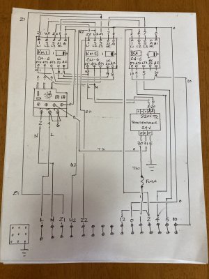
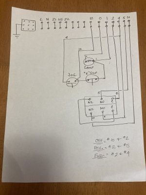
I have not included the motor wiring scheme on the second drawing .
Also the way this is wired , as it originally came , the "E" stop only kills the directional control circuits , the power on lamp is illuminated and the transformer is powered up at all times as long as the machine is plugged in to the wall recepticle and the breaker is on . This is why I always turn off the breaker or un plug the machine when it is not being used .
I should add at this point the L & N wires come off the terminal strip and run to the thermal overload relay , I have identified them incorrectly in my drawing , what the little yellow man has done when it was wired up at the factory is , he marked the opposite ends of those two wires like this ..... the one end is "L ", the other end is marked "N" , both wires of that pair is marked like that.


I have not included the motor wiring scheme on the second drawing .
Also the way this is wired , as it originally came , the "E" stop only kills the directional control circuits , the power on lamp is illuminated and the transformer is powered up at all times as long as the machine is plugged in to the wall recepticle and the breaker is on . This is why I always turn off the breaker or un plug the machine when it is not being used .
Gearhead88
Ultra Member
Yes , I did all of those tests , weeks ago , several times , verifying that I have 120 v at both and to the contactors as well as the transformer , the transformer isn't all that accurate , it puts out around 30volts on the output side.On this machine, instead of labelling L2 as L2, they left it as N. On this machine, there is no neutral. Probably a universal diagram because the machine was possibly offered in a 120v version as well. Either way, it doesn't matter.
In this case, measuring L1 to ground, or N (actually L2) to ground should each show 120v, and 240v L1 to N (L2)
Test for 120v, 240v where it should be, test for proper 24vac where it should be, and test the motor directly to 240v, and you'll find your problem.
30 volts shouldn't be a problem.Yes , I did all of those tests , weeks ago , several times , verifying that I have 120 v at both and to the contactors as well as the transformer , the transformer isn't all that accurate , it puts out around 30volts on the output side.
with the motor disconnected at the terminal strip, you can plug the machine in, and operate the controls, and check output voltage at the respective contactors
Gearhead88
Ultra Member
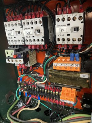
Here's an overview of the electrical box .
Some of you will look , and wonder what the white wire is for , as part of the power feed in to the box ? , It's because I added 110 volt recepticle for a work light .
My milling machine , when I received it , the same day as the lathe back in 2004 called for a four wire plug , it has a 110 recepticle on the side for a work light , a power feed and the coolant pump is 110 volt too , my welder also has a 110 volt recepticle on the side of it , this is why all three machines have a four wire plug.
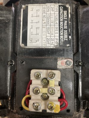
Here's the old motor ............
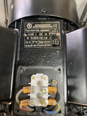
Here's the new motor ..........
Some of you will look , and wonder what the white wire is for , as part of the power feed in to the box ? , It's because I added 110 volt recepticle for a work light .
My milling machine , when I received it , the same day as the lathe back in 2004 called for a four wire plug , it has a 110 recepticle on the side for a work light , a power feed and the coolant pump is 110 volt too , my welder also has a 110 volt recepticle on the side of it , this is why all three machines have a four wire plug.

Here's the old motor ............

Here's the new motor ..........

Last edited:
Gearhead88
Ultra Member
I've done that too . and will do it again , maybe tonight , I need to put it back together , It was not behaving when it was all assembled on the back of the machine , as though one of the contactors was buggered. It's all on the bench now and with an ohmmeter connected to the contactor high voltage terminals I can manually operate each contactor and it behaves as it should , completing the circuit as it is designed.30 volts shouldn't be a problem.
with the motor disconnected at the terminal strip, you can plug the machine in, and operate the controls, and check output voltage at the respective contactors
Gearhead88
Ultra Member
Yup , that' s how it's wired , I got the mill running first in 2004 and since that require four wires I thought , I'd wire the lathe the same and add the 110 outlet.as long as that neutral only goes to the receptacle, it shouldn't cause any issues, and is good to have.
Gearhead88
Ultra Member
Something else that messes with me is the way the motor is connected , look at the two pictures I just posted , the older motor has those connecting strips and six terminals .
I look at that all slack jawed .
The new motor has four terminals
I look at that all slack jawed .
The new motor has four terminals
Last edited:
Gearhead88
Ultra Member
I need to go out there and mess with it , I use my desk top in the house to post and read this .
I need to test capacitors and motor windings again , next .
At the beginning of this whole debacle I bought a motor , installed it and all I got was a loud hum .
Now , could this be because I hooked up the motor incorrectly ? , It's entirely possible , the two motors have very different terminals as seen by the eyes of a guy who is in unfamiliar territory.
Gearhead88
Ultra Member
I was outside and took some measurements
Brand new start cap = 226.4 uF
Brand new run cap = 25.92 uF
Old motor Start cap = 107.9 uF ( seems afoul to me)
Old motor run cap = 24.41 uF
Old motor U1 - U2 = 1.0 ohm
Old motor V1 - V2 = 1.0 ohm
New motor start cap = 233.4 uF
New motor run cap = 35.26 uF
New motor U1 - U2 = 1.7 ohms
Brand new start cap = 226.4 uF
Brand new run cap = 25.92 uF
Old motor Start cap = 107.9 uF ( seems afoul to me)
Old motor run cap = 24.41 uF
Old motor U1 - U2 = 1.0 ohm
Old motor V1 - V2 = 1.0 ohm
New motor start cap = 233.4 uF
New motor run cap = 35.26 uF
New motor U1 - U2 = 1.7 ohms
Gearhead88
Ultra Member
Okay , That was what I had planned on doing this evening and yes the shop beer fridge is stocked . I have some re-assembly to do first .I'd change the caps on the old motor and toss it in, and try it. Hope you have a cold beer on hand.
Something else I've noticed is , at the beginning of this I found some broken plastic schrapnel in the bottom of the cabinet , it came from the end of the terminal strip where all the connections are made , Yes it's damaged and has been that way for a very long time , probably since being built , since it was laying in a smear of leaked oil from the gearbox . The quality of workmanship is low and the skill or perhaps the level of care is just not there with this stuff , e.g. , din rails crudely cut off all ragged , the wires that were marked all goofy , this thing seeps oil from several locations , crude , shitty pourus castings .
Gearhead88
Ultra Member
Monday morning way too much sake on the weekend.
Good work on the measuring, things became a lot clearer, it can be tough sometimes when you don't have something to compare it too.
Good work on the measuring, things became a lot clearer, it can be tough sometimes when you don't have something to compare it too.
Gearhead88
Ultra Member
And spending an entire career working on low voltage DC stuff , being nearly oblivious about AC motors . I’ve always had success working on Cranes , Snow Cats and allMonday morning way too much sake on the weekend.
Good work on the measuring, things became a lot clearer, it can be tough sometimes when you don't have something to compare it too.
Manner of road or off road vehicles

