I had to download it to get a smooth video. My internet connection isn't fast enough for that kind of resolution.Is that video really choppy for anyone else?
-
Scam Alert. Members are reminded to NOT send money to buy anything. Don't buy things remote and have it shipped - go get it yourself, pay in person, and take your equipment with you. Scammers have burned people on this forum. Urgency, secrecy, excuses, selling for friend, newish members, FUD, are RED FLAGS. A video conference call is not adequate assurance. Face to face interactions are required. Please report suspicions to the forum admins. Stay Safe - anyone can get scammed.
-
Several Regions have held meetups already, but others are being planned or are evaluating the interest. The Calgary Area Meetup is set for Saturday July 12th at 10am. The signup thread is here! Arbutus has also explored interest in a Fraser Valley meetup but it seems members either missed his thread or had other plans. Let him know if you are interested in a meetup later in the year by posting here! Slowpoke is trying to pull together an Ottawa area meetup later this summer. No date has been selected yet, so let him know if you are interested here! We are not aware of any other meetups being planned this year. If you are interested in doing something in your area, let everyone know and make it happen! Meetups are a great way to make new machining friends and get hands on help in your area. Don’t be shy, sign up and come, or plan your own meetup!
You are using an out of date browser. It may not display this or other websites correctly.
You should upgrade or use an alternative browser.
You should upgrade or use an alternative browser.
CT 043 issues ..... Repairs - Completed !!
- Thread starter Gearhead88
- Start date
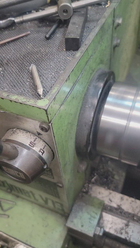
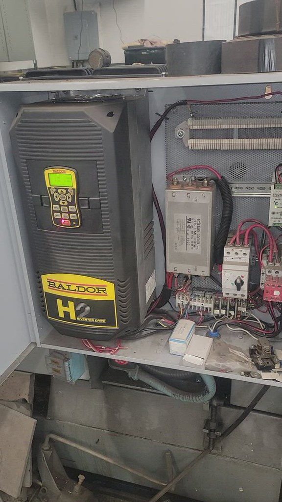
i have a few more i just took, to illustrate some points of a ok-ish vfd install.
 20220131_213843 by Darren Floen, on Flickr
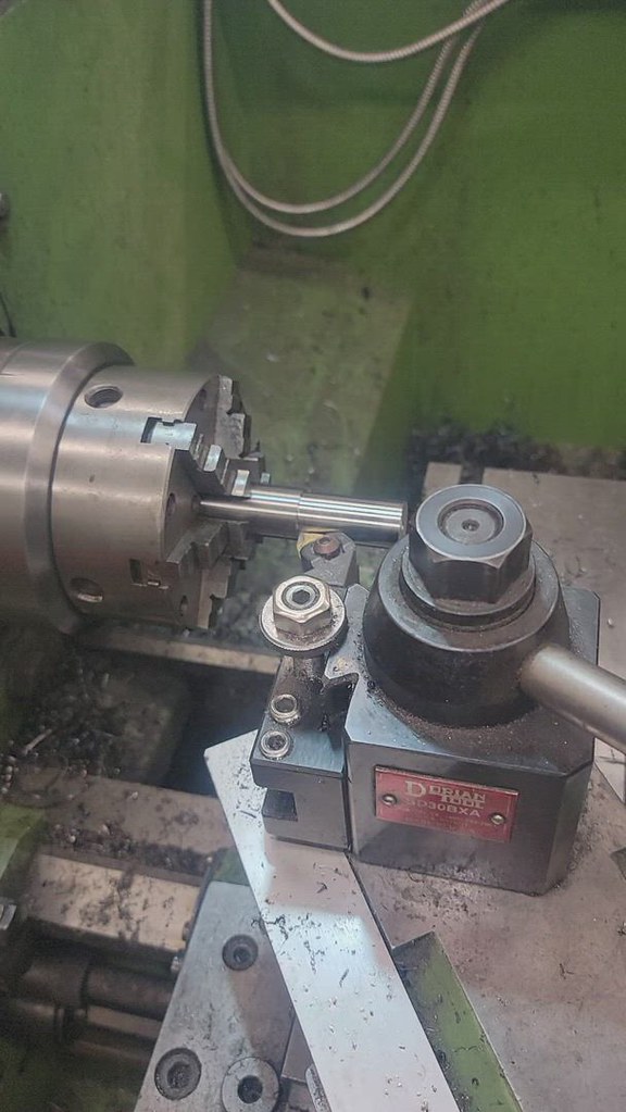
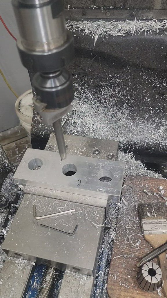
This is THE WORST material i could have picked for a demo. Its chromolly and its a bastard, but it illustrates that a fine adjustment can make a big difference in finish, chip control, etc
 20220131_214042 by Darren Floen, on Flickr
 20220131_214220 by Darren Floen, on Flickr
 20220131_214258 by Darren Floen, on Flickr
 20220131_214623 by Darren Floen, on Flickr
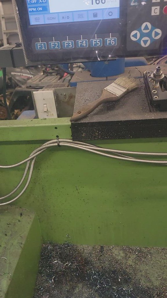
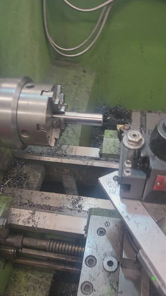
anyways, hope the videos work, i'm just messing around in the shop tonight, and thought i'd show why i like VFD's so much. I'll fire up the big lathe if someone wants, and show the other reason i like vfd's
Edit, alright, I talked me into it:
 20220131_223823 by Darren Floen, on Flickr
20220131_213843 by Darren Floen, on FlickrThis is THE WORST material i could have picked for a demo. Its chromolly and its a bastard, but it illustrates that a fine adjustment can make a big difference in finish, chip control, etc
20220131_214042 by Darren Floen, on Flickr20220131_214220 by Darren Floen, on Flickr20220131_214258 by Darren Floen, on Flickr20220131_214623 by Darren Floen, on Flickranyways, hope the videos work, i'm just messing around in the shop tonight, and thought i'd show why i like VFD's so much. I'll fire up the big lathe if someone wants, and show the other reason i like vfd's
Edit, alright, I talked me into it:
20220131_223823 by Darren Floen, on Flickr
Last edited:
i have a few more i just took, to illustrate some points of a ok-ish vfd install.
This is THE WORST material i could have picked for a demo. Its chromolly and its a bastard, but it illustrates that a fine adjustment can make a big difference in finish, chip control, etc
anyways, hope the videos work, i'm just messing around in the shop tonight, and thought i'd show why i like VFD's so much. I'll fire up the big lathe if someone wants, and show the other reason i like vfd's
Edit, alright, I talked me into it:
Gesus @dfloen. Sometimes I can be a total idiot.
I already noticed I can fine tune finish by using the "on the fly" speed control of a VFD on my pulley drive mill. NICE!
But for cerebral deficiency reasons that only my wife understands (and reminds me regularly), I never really thought of the advantages of doing that on my lathe too. I even noticed you doing it in your first video and I actually commented on how cool it was. BUT...... that particular neural connection was totally blocked by my personal goal of achieving lower speed.
Your second set of videos overcame my blindness and drove the point home in a much better way. Suddenly I realize (and have fully assimilated) the idea that speed adjustment ON THE FLY (higher and lower) is a worthy goal all on its own on the lathe too!
THANK YOU SIR Darren!!!
I think I'll move that lathe vfd project a bit further up my priority list.....
anyways, hope the videos work, i'm just messing around in the shop tonight, and thought i'd show why i like VFD's so much. I'll fire up the big lathe if someone wants, and show the other reason i like vfd's
Very nice Darren. A GREAT set of videos for illustrative purposes. I don't see how anyone could watch those and not be convinced of the merits of a VFD.
A few questions:
Is that brake that keeps "popping" in and out automatic? If you use the direction controls of the VFD, does it still engage? Or does it just smoothly slow down and change direction?
I noticed that you can really feel (hear) the inertia in that big lathe on your last video. Especially coasting along without any load. Did that happen before you installed the VFD too?
Gearhead88
Ultra Member
You make a good salesman Darren , I think I'm gonna do this . After watching all your vid's It is obvious there are so many benefits .
I was looking both on ebay and Amazon at VFD's yesterday .
I need to make good decisions on what to buy and then there is the motor , I'll need to find one that will fit this application
Thank's for the videos and all the advice you've provided , I'm inspired !
I have a Busy bee Knee mill that I use quite a bit and has been trouble free for nearly 18 years , I've toyed with the idea of using it for seat and guide work but it has limitations due to the belt drive and not being able to drop the speed down to a useable RPM . I do use it for cylinder head work to do specific operations but due to the speed issue it is limited for now on what I can do with it. This is a B048 , there is no reverse either . I can see a VFD conversion as an awesome update for this little mill . The pics are my home shop .


The above pic is ported Jeep 4.0 l head , converted to run oversize valves , I did up two of them , beehive springs for an LS chev , comp cams camshaft , 4.0 l block with a 4.2 crank , makining it a 4.7 l ( +.060" overbore) . This was around 2006 ish when I was a Jeep nut and in an off road club.
I work part time now at a Motorcycle shop , I gotta admit , I've been a lifelong motorcycle nut , there's two of us doing performance Engine work , transmission , clutch and dyno tuning , there are other guys working there that do the general maintenance and repair work.
I was looking both on ebay and Amazon at VFD's yesterday .
I need to make good decisions on what to buy and then there is the motor , I'll need to find one that will fit this application
Thank's for the videos and all the advice you've provided , I'm inspired !
I have a Busy bee Knee mill that I use quite a bit and has been trouble free for nearly 18 years , I've toyed with the idea of using it for seat and guide work but it has limitations due to the belt drive and not being able to drop the speed down to a useable RPM . I do use it for cylinder head work to do specific operations but due to the speed issue it is limited for now on what I can do with it. This is a B048 , there is no reverse either . I can see a VFD conversion as an awesome update for this little mill . The pics are my home shop .
The above pic is ported Jeep 4.0 l head , converted to run oversize valves , I did up two of them , beehive springs for an LS chev , comp cams camshaft , 4.0 l block with a 4.2 crank , makining it a 4.7 l ( +.060" overbore) . This was around 2006 ish when I was a Jeep nut and in an off road club.
I work part time now at a Motorcycle shop , I gotta admit , I've been a lifelong motorcycle nut , there's two of us doing performance Engine work , transmission , clutch and dyno tuning , there are other guys working there that do the general maintenance and repair work.
DPittman
Ultra Member
FWIWYou make a good salesman Darren , I think I'm gonna do this . After watching all your vid's It is obvious there are so many benefits .
I was looking both on ebay and Amazon at VFD's yesterday .
I need to make good decisions on what to buy and then there is the motor , I'll need to find one that will fit this application
Thank's for the videos and all the advice you've provided , I'm inspired !
I have a Busy bee Knee mill that I use quite a bit and has been trouble free for nearly 18 years , I've toyed with the idea of using it for seat and guide work but it has limitations due to the belt drive and not being able to drop the speed down to a useable RPM . I do use it for cylinder head work to do specific operations but due to the speed issue it is limited for now on what I can do with it. This is a B048 , there is no reverse either . I can see a VFD conversion as an awesome update for this little mill . The pics are my home shop .
View attachment 20569
View attachment 20570
The above pic is ported Jeep 4.0 l head , converted to run oversize valves , I did up two of them , beehive springs for an LS chev , comp cams camshaft , 4.0 l block with a 4.2 crank , makining it a 4.7 l ( +.060" overbore) . This was around 2006 ish when I was a Jeep nut and in an off road club.
I work part time now at a Motorcycle shop , I gotta admit , I've been a lifelong motorcycle nut , there's two of us doing performance Engine work , transmission , clutch and dyno tuning , there are other guys working there that do the general maintenance and repair work.
I have a similar busybee mill that I converted to vfd and really like it. I used cheap Amazon vfds and so far all is good.
Is that brake that keeps "popping" in and out automatic? If you use the direction controls of the VFD, does it still engage? Or does it just smoothly slow down and change direction?
I noticed that you can really feel (hear) the inertia in that big lathe on your last video. Especially coasting along without any load. Did that happen before you installed the VFD too?
Thats the brake. I need to fine tune it a bit more. Right now it comes on at 18hz, so the vfd is set for 20-120hz, so when stopping the vfd brakes to 18 then the brake comes on. I'm going to play with it more when i have time. Its all easily tuneable, but this works pretty decent.
The big lathe has a big brake resistor and a electro brake as well, it just has 20 times the inertia to stop. That and the vfd will trip on decel sometimes, so i had to extend the braking time.
Gearhead88
Ultra Member
Here's what I have for now , this is the Label on the motor that came with the Mill , I can take some pics of the switch and the inside of that housing shortly.hit me up with a pic of your mill rating plate

Thats the brake. I need to fine tune it a bit more. Right now it comes on at 18hz, so the vfd is set for 20-120hz, so when stopping the vfd brakes to 18 then the brake comes on. I'm going to play with it more when i have time. Its all easily tuneable, but this works pretty decent.
The big lathe has a big brake resistor and a electro brake as well, it just has 20 times the inertia to stop. That and the vfd will trip on decel sometimes, so i had to extend the braking time.
Good stuff! My lathe has no brake but I'd like one. A braking resistor run with the VFD should do what I want.
I've toyed with the idea of using it for seat and guide work but it has limitations due to the belt drive and not being able to drop the speed down to a useable RPM .
Yup, you will LOVE what a VFD can do for your mill. To be most effective you will also need a 3phase motor.
I put one on my Hartford mill. The result was amazing....
Gearhead88
Ultra Member
I have both motors on the bench .Where are we at with getting the lathe running again?
I've got the electrical box taken apart to look at it on the bench .
I've checked out the contactors for continuity with a digital multimeter and they appear to be good.
I have more contactors coming from the land of China but it seems there is a big delay due to Chinese new year that wont get me those parts anytime soon .
I do have a new thermal overload relay , a pair of new capacitors and a new motor here that is possibly NFG ? , I don't mind having a few spare parts on hand
It turns out the meter I had in my motor home that measures capacitance doesn't measure up to the value of the start capacitor , it does measure lower value's and I've been able to test the run capacitors .
Today , I'm going to work to get some parts for another project I have going and to get my other meter , which is a nice Snapon , I believe that one will work for measuring the start capacitors, it's a nice meter I almost had to take out a mortgage to buy it.
I have a confusing (go figure ) possible glitch with the way this machine was wired from new and the way a couple of wires were labeled and routed , It looks like the "L" & "N" wires are labelled weird and are crossed . It's a head scratcher ????
Yesterday , I had the forward / reverse lever , rod / linkage and associated parts off to tighten up the slop in it , that was a success .
The VFD conversion is a great idea , it may have to wait , I have other fish to fry .
So , to answer your question , most of what is needed to fix it is here . I kinda wish I had another set of eyes and a second opinion , some day , yes it will run again .
Last edited:
I have a confusing (go figure ) possible glitch with the way this machine was wired from new and the way a couple of wires were labeled and routed , It looks like the "L" & "N" wires are labelled weird and are crossed . It's a head scratcher ????
It isn't unusual for an idiot to reverse the line and neutral wires. This will actually work just fine unless or until there is a ground fault.
It is an AC system so from a voltage perspective the two are constantly swapping positions anyway.
For safety sake, you should check them thoroughly and correct them if necessary.
It's at least conceivable that this might also explain your problems. If the neutral is grounded or even just bonded, and also reversed, this could feed current back to your sub-panel if it isn't wired correctly, or even all the way back to your main panel where the neutral is supposed to be grounded.
Over the years, I've seen lots of off shore stuff reversed and I've met more than the odd electrician who didn't understand this either.
Oh and the 'potentially mislabeled L & N wire, well the lathe will still operate, as it has been since you've purchased it.
I'd think if they were crossed the potential impact would be to just cause the two contactors to operate the opposite as intended, but I haven't look at the diagram yet so dont hold me to anything there.
Even without looking at the wiring, I doubt that the contactors would be affected.
AC contactors would not know the difference and DC contactors would be powered by a rectified DC voltage that wouldn't know the difference either.
The only point i'm trying to make is that regardless of the wiring diagram, the machine can easily be diagnosed. Theres a physical diagram right there. There's no electronics here, just some simple components to test, follow the power from the cord to the motor. Verify that whichever motor is installed actually works. Hook power direct. Once verified, it can be used as a load for all further testing.
Gearhead88
Ultra Member
Just to clarify
I'm the original owner , I did change the motor not long after it was new as a warranty item , it has run well and been a great lathe since then and there have been no other operators at all .
There have been no alterations to it , I bought it new in 2004 just like you see it.
The thermal overload relay has always been connected as you see it in the pictures.
The crossed and miss - labelled wires are something I noticed recently .
I have tested all three contactors with an ohmmeter for continuity and correct function .
I tested the run capacitor on the motor I've been using for the last 17 + years , it's good .
I just got home from picking up my other meter and I'm going out to the garage to check the start capacitor .
I had the old motor apart yesterday and had a look at the centrifugal switch , also looked for burnt wires , any evidence of anything nasty or burned and I checked the continuity of the windings with an ohmmeter. I will repeat some of these tests again today with the meter i just went to work and picked up. and report back with the readings I get.
I am going to remove the two wires that the little yellow man marked with a sharpie , take pictures of them to prove that they have *****wits wiring this junk.
I'll be back
isn't this a 240v machine? ie, no neutral, just 2 hots
I don't know about this particular machine. I'm just contributing ideas and food for thought. Many 240v machines have 2 hot wires and some have the neutral wire too. And some that have the neutral don't use it. There are lots of possible combinations.
Again, just suggesting things that occur to me as possibilities to look at. They may or may not help.
On this machine, instead of labelling L2 as L2, they left it as N. On this machine, there is no neutral. Probably a universal diagram because the machine was possibly offered in a 120v version as well. Either way, it doesn't matter.I don't know about this particular machine. I'm just contributing ideas and food for thought. Many 240v machines have 2 hot wires and some have the neutral wire too. And some that have the neutral don't use it. There are lots of possible combinations.
Again, just suggesting things that occur to me as possibilities to look at. They may or may not help.
In this case, measuring L1 to ground, or N (actually L2) to ground should each show 120v, and 240v L1 to N (L2)
Test for 120v, 240v where it should be, test for proper 24vac where it should be, and test the motor directly to 240v, and you'll find your problem.