• Scam Alert. Members are reminded to NOT send money to buy anything. Don't buy things remote and have it shipped - go get it yourself, pay in person, and take your equipment with you. Scammers have burned people on this forum. Urgency, secrecy, excuses, selling for friend, newish members, FUD, are RED FLAGS. A video conference call is not adequate assurance. Face to face interactions are required. Please report suspicions to the forum admins. Stay Safe - anyone can get scammed.

Collet questions

Susquatch

Ultra Member
Administrator
Moderator
Premium Member
..... there isn't really much downside to a longer thread engagement....

There is one downside that happens sometimes. Once in a while you encounter an R8 Arbour that isn't drilled or threaded through.

As PeterT noted earlier, in this circumstance a long drawbar thread can bottom out with relatively bad consequences.

It's a good thing to try to remember.
 

mbond

Well-Known Member
Premium Member
Yes, when he said that, a lot of the bad things that people reported on this thread made a lot more sense. The friction from the taper should hold all of the load, but if you can't apply any normal force (because the bar has come to the end of the thread) it can't take any.

My machine has an MT3 and can't break screws like this, but I had to remake the stock draw bar for exactly this reason. I just figured that my machine was cheap
 

Susquatch

Ultra Member
Administrator
Moderator
Premium Member
My machine has an MT3 and can't break screws like this, but I had to remake the stock draw bar for exactly this reason. I just figured that my machine was cheap

I just today made a collar spacer for @CWret. It serves two purposes. One is to make the drawbar seem a little shorter, and the second is to center the drawbar in the spindle. Most drawbars have a lot of slop inside and I find it sometimes causes them to vibrate and even to rattle in others. I first did that on my own old mill/drill which had an mt3 taper too. I've made one for quite a few other machines now.

Once you have one sleeve, you can just add washers if you need it even shorter or you can make a few other sizes of sleeves.
 

whydontu

I Tried, It Broke
Premium Member
Advice please - instead of the 1/8” drawbar spacer I’m using (post 67 above, picture below).

Any reason i shouldn’t just shorten the drawbar?

CW
Hard to make the drawbar longer once you cut it. Drawbar = $$$$$, washer = ¢¢

And making a nice spiffy centering washer gives you a reason to spend time using a lathe
 

Susquatch

Ultra Member
Administrator
Moderator
Premium Member
Hard to make the drawbar longer once you cut it. Drawbar = $$$$$, washer = ¢¢

And making a nice spiffy centering washer gives you a reason to spend time using a lathe

You are right. Bad idea to shorten a drawbar.

But poor devil doesn't have a lathe...... Yet anyway....... LOL!

He did send me the dimensions and I made him one today. It will go in the mail tomorrow.
 

Susquatch

Ultra Member
Administrator
Moderator
Premium Member
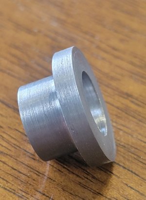
I am headed off to the post office this morning to mail this drawbar centering collar to @CWret. But I thought I would post a photo and a description first because this one is a bit different from others I have made and probably more typical of the average bench top mill out there.

20231120_092111.jpg

As mentioned earlier, the collar serves two purposes - to center the draw bar inside the spindle, and space the drawbar up a bit so it doesn't thread as deeply into R8 Arbours. One can always add washers or custom spacer collars to add additional spacing if needed.

The main reason for adding this post is to briefly discuss the need to accommodate rolled threads on the drawbar.

Rolled threads are a fast and easy way to make threaded fasteners in industry that reduces waste. The threads are not cut and produces no swarf. Instead the rolling process displaces metal and the outside diameter of the threaded section gets bigger than the shaft they are rolled on. To accommodate this diameter growth, the shafts are deliberately undersized so they can grow to the target thread dimensions.

In the case of a drawbar with rolled threads, that means that the drawbar itself has a smaller shaft than the OD of the threads. As a result, one cannot simply slip a centering collar over the threads because anything that can clear the threads will be a loose fit at the top of the drawbar, which at least partially defeats the purpose of centering the drawbar inside the spindle.

The solution is to size the collar ID to fit the shaft, and then cut threads in it to clear the rolled threads of the shaft. The collar is then simply spun on over the threaded end until it clears the threaded section and then it will slide over the rest of the rod. Problem solved.

In CWret's case, the drawbar threads are cut, not rolled. Therefore the collar I made for him is not threaded. The threads on my Hartford Clone drawbar are rolled. So my collar is threaded.
 

CWret

Ultra Member
Premium Member
Your solution above works fine, but as i understand it, the stationary collar threads would be rubbing on the rotating drawbar.
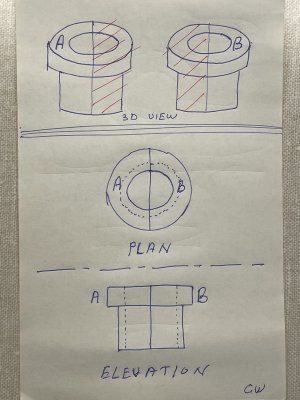
Another way, but a little more work, is to make split rings. For this solution you’d have to make 2 identical collars. Machine and discard half of both.
75CD00D8-97D0-45F6-8964-2FD8FF8A7610.jpeg
 

CWret

Ultra Member
Premium Member
ooops - it was a quick sketch- dotted lines on the elevation are too far apart.
 

Susquatch

Ultra Member
Administrator
Moderator
Premium Member
Your solution above works fine, but as i understand it, the stationary collar threads would be rubbing on the rotating drawbar.

The collar, drawbar, spindle, and R8 Arbour all turn as one single unit. No thread rubbing to worry about.

The only time they might rub is when the drawbar is first rotated to engage the arbour threads.

But, since the collar is only threaded to a very shallow depth - always less than 50% of nominal, which itself is prolly only 75%, you are talking about something around 20 to 30% threaded and 70 to 80% cylindrical. That is more or less smooth cylinder on round drawbar. A little oil on the collar and the 20/30% spiral grooves will act like oil reservoirs.

In other words, its nothing I'm ever gunna worry about.

There is however an advantage to having split collars. The drawbar doesn't have to lifted right out to install a split collar, and any threads - rolled or otherwise, can't ever be an issue.
 

CWret

Ultra Member
Premium Member
Yes - i very much appreciate @Susquatch making the part for me.
I certainly already thanked him but it was in a PM - so here I’m letting everyone know my appreciation.
:) Thank you Susquatch!

The collar, drawbar, spindle, and R8 Arbour all turn as one single unit. No thread rubbing to worry about.
OK - i get it now. Good explanation.
My inexperience showing through again.
 

whydontu

I Tried, It Broke
Premium Member
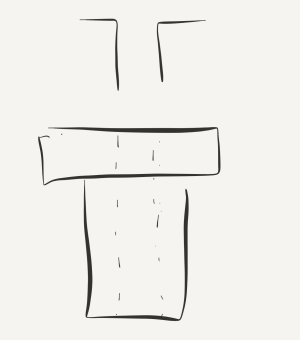
Or three piece - solid shoulder bushing that clears the thread, split sleeves that take up the shaft clearance.

IMG_6874.jpeg
 

Susquatch

Ultra Member
Administrator
Moderator
Premium Member
Or three piece - solid shoulder bushing that clears the thread, split sleeves that take up the shaft clearance.

The shaft clearance is very little. I don't think you have room for two or three layers in there.
 

Dabbler

ersatz engineer
Another way would be to split the material first, bolt or tack weld it back together then machine it to size.
If you turn it 2 pieces in the lateh, you just hold them in a 4J chuck without welding or gluing. After the turning and parting, they are ready.

*** if you are tapping using the 4J this way *** you use a hose clamp to help oppose the forces, as they are hanging out of the chuck. Or you can use a C clamp, or a kant-twist clamp. If you do this, then you drill/tap first, then turn to round. (after removing the clamp :eek:)
 

Tomc938

Ultra Member
Premium Member
OMG!!!!

...so that you can loosen or tighten your holder not to act as a driver.
If you are talking about the pin that aligns with the slot on the R8 collet, I would beg to differ. Well, not me personally, because I know almost nothing. But as the pin on my "new" mill is severely buggered up, I've been researching options on fixing it.

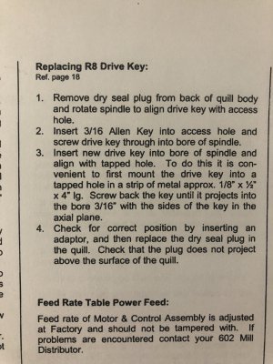
In my "Ex-Cell-O Style 602 Ram Turret Milling Machine Manual", page 8, I found the instructions for "Replacing R8 Drive Key". This leads me to believe that the people who manufactured my mill believe that the key that engages the slot on the R8 collet is, in fact, a drive key. This leads me to believe that the key drives something.
IMG_0079.JPG

BTW: They did an excellent job of designing this. It's an easy replace, which makes me think @Susquatch isn't the only one shearing it off.
 

Dabbler

ersatz engineer
In several PM conversations on this: I personally have used about 12 BP style mills 5 in professional settings and 7 in home shops. Not one was sheared. But @Susquatch has had the opposite experience in his scope. Others have had mixed results. So I think it is a wash.

But it should be a fairly simple fix. Some guys hate the pin. Some guys love the pin (me!) and some just don't care.
 

PeterT

Ultra Member
Premium Member
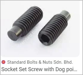
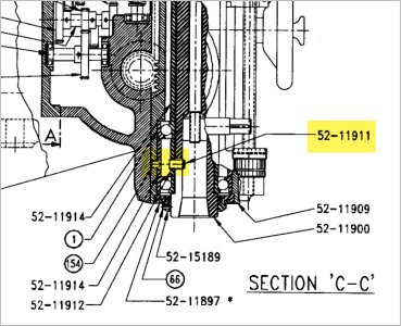
I have also seen references to the word 'key' pertaining to R8 slot on Bridgeport mills. Which has me wondering if some of the Asian clones have taken a shortcut with a dog point set screw & Bridgeports have something different? Or is it just that there are different interpretations/definitions of the word 'key'? I Googled your mill manual but not sure, is this the corresponding diagram that accompanies your description? It doesn't really show the part (52-1191) in much detail, but from what you know, is it circular section dog point looking part? Or does it have some kind of squared off section?

If a Bridgeport or Excello its essentially the same screw then I think this discussion is more about semantics. Key might mean something that slides within a slot & provides some resistance to torque. How much torque or what specific load purpose they don't say, they just give it a name & instructions to replace. There are keys like on shaft/gear assembly which are more tight fitting, significantly more surface area & not really designed to slide the parts off 100 times a day. They are designed to take up all or at least majority of drive torque. There are also keys like a padlock or door knob which are looser fit, repetitious in/out intending to rotate a tumbler when properly engaged (but not much more torque if its a mismatched key). I still think this R8 mill part qualifies as a looser fitting 'indexing/alignment key' designed to resist some lesser torque until the drawbar eventually forces the tapers together. I think if they really wanted a normal, rectangular key for the R8 slot, they would have integrated it into the spindle. But all I know for certain is my machine has a dog point.

1701062869884.png


Attachments

  • EDT-26-11-2023 10.22.28 PM.jpg
    EDT-26-11-2023 10.22.28 PM.jpg
    109.6 KB · Views: 3
Top