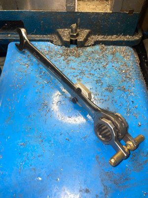
A question about your drawbar wrench. Why does it have the two brass pieces on it?
-
Scam Alert. Members are reminded to NOT send money to buy anything. Don't buy things remote and have it shipped - go get it yourself, pay in person, and take your equipment with you. Scammers have burned people on this forum. Urgency, secrecy, excuses, selling for friend, newish members, FUD, are RED FLAGS. A video conference call is not adequate assurance. Face to face interactions are required. Please report suspicions to the forum admins. Stay Safe - anyone can get scammed.
-
Several Regions have held meetups already, but others are being planned or are evaluating the interest. The Calgary Area Meetup is set for Saturday July 12th at 10am. The signup thread is here! Arbutus has also explored interest in a Fraser Valley meetup but it seems members either missed his thread or had other plans. Let him know if you are interested in a meetup later in the year by posting here! Slowpoke is trying to pull together an Ottawa area meetup later this summer. No date has been selected yet, so let him know if you are interested here! We are not aware of any other meetups being planned this year. If you are interested in doing something in your area, let everyone know and make it happen! Meetups are a great way to make new machining friends and get hands on help in your area. Don’t be shy, sign up and come, or plan your own meetup!
You are using an out of date browser. It may not display this or other websites correctly.
You should upgrade or use an alternative browser.
You should upgrade or use an alternative browser.
Collet questions
- Thread starter slow-poke
- Start date
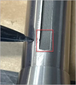
I might be reading more into this or incorrectly viewing, but it almost appears your dog point position might be within the shallower depth slot radius range vs higher up in the full slot depth? It may not be a mill issue, it may be a collet/tooling issue. This is exactly what has caused me grief in the past - the slot dimensions have deviated from the so called standards.
The dent kind of speaks for itself & this is what I was trying to say before - I don't think the intent of the dog point is to be a 'key' in the classic sense of a shaft key where it takes the entire torque load. A key has significantly more surface contact area & meat. I think the dog point is there to fingerhold the collet from rotation while being drawn up into the conical seat. Once in contact with the seat, friction takes over as its clamping the tool shank. Some use the dog point, some experience more problems & remove it altogether. Some use it in manual tighten mode, but remove it with powered tighteners. This might demonstrate why, every time that collet gets used, the position of the dent is the same & can grow & eventually become more problematic. Soft collets & soft screws would also contribute to problems.
The dent kind of speaks for itself & this is what I was trying to say before - I don't think the intent of the dog point is to be a 'key' in the classic sense of a shaft key where it takes the entire torque load. A key has significantly more surface contact area & meat. I think the dog point is there to fingerhold the collet from rotation while being drawn up into the conical seat. Once in contact with the seat, friction takes over as its clamping the tool shank. Some use the dog point, some experience more problems & remove it altogether. Some use it in manual tighten mode, but remove it with powered tighteners. This might demonstrate why, every time that collet gets used, the position of the dent is the same & can grow & eventually become more problematic. Soft collets & soft screws would also contribute to problems.
Attachments
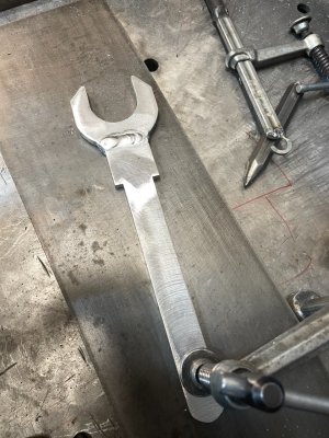
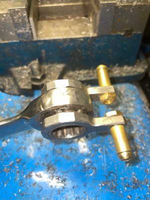
Good question @jcdammeyer , I forgot that the video didn’t explain/show the purpose of the brass handles. There is one facing up and one down to act as a speed wrench by using that function of the ratchet wrench (forward and reverse). The ratchet wrench I used is a 22mm size. I cut out the wrench teeth to match the OD of a 3/4” deep socket. Then welded in the deep socket. It was a deep socket so that i could attach the speed wrench brass handles (pieses of brass tubing). This video (below) shows it better but i forgot to turn off my shop radio - so please put on mute so as to keep me out of jail. I could just have simply use a 3/4” ratchet wrench - but what fun is there in that!!
Here’s a couple of pics of the brass handles and the aluminum wrench.
Here’s a couple of pics of the brass handles and the aluminum wrench.
Attachments
Last edited:
I agree. I only did this once, as I said above, and then I carefully used a fine file and a stone to remove the dimples. They have not reappeared since i now always use the 2 wenches.The dent kind of speaks for itself & this is what I was trying to say before - I don't think the intent of the dog point is to be a 'key' in the classic sense of a shaft key where it takes the entire torque load
One dimple was due to tightening and the other for loosening.
I might be reading more into this or incorrectly viewing, but it almost appears your dog point position might be within the shallower depth slot radius range vs higher up in the full slot depth? It may not be a mill issue, it may be a collet/tooling issue. This is exactly what has caused me grief in the past - the slot dimensions have deviated from the so called standards.
Peter - I believe you are exactly right. @CWret's contact is a triffle lower towards the table than mine is. Mine might be more like the top of the red box you drew.
As we have discussed earlier, it's clear to me that the grub screw cannot hold the collet alone. Based on a very rough calculation, it's shear strength is only sufficient to hold about 100 ft-lbs. (200 for my wide pin). That's more than enough to hold against an average drawbar tightening torque of 30 ft-lbs. But compare that to the tapers torque holding capacity of around 2000 ft-lbs for 30 ft-lbs on the drawbar. Nonetheless, 10% is still 10% more than with no pin. Its also free torque that is independent of the drawbar tension.
@CWret has already noted that he dimpled the collet tightening and loosening the drawbar.
Personally, I have come to the conclusion that broken pins are the result of undertorquing the drawbar. I have a peak recording torque gauge. It seems I average around 25 ft-lbs even with my size. I can do 30 no trouble but it seems I usually don't. 50 with a 12in wrench is doable but more than I am comfortable doing. This morning a 5 and a half foot neighbour dropped by and I asked him to tighten it to his ability. He only hit 16 ft-lbs (half the recommended 30). I would easily imagine that torque is highly sensitive to how far above their head the drawbar is. Add some residual oil to the taper and I think that spells broken alignment screws.
My advice is to get a torque wrench and use it. Oil the drawbar threads, but keep the collet and spindle clean.
I don't think I'll ever break a pin - especially not my double wide pin, but I can't speak for others, and never say never!
Btw - according to my notes, the recommended drawbar torque is 20 ft lbs for small tools, 30 on average, and 40 for large ones.
Another thing I have experienced is a shallower than normal drawbar thread depth. The drawbar bottoms out, you think you are good (as in collet seated). Start machining & bad things happen. I measured all my R8 tooling & discovered they vary. Now part of this could have been slightly longer drawbar when I upgraded mills. Anyways I made a spacer washer for the top of my drawbar. It still has plenty of thread engagement.
Yep - happened to me first time i used my new, outta the box, boring bar head and boring bar set. Fortunately i was using a very small bar - it jumped, banged and bent - it’s scrap.The drawbar bottoms out, you think you are good (as in collet seated). Start machining & bad things happen.
Added a spacer as you did. Now, as a general rule, i check every new tool before pushing the holy sh@t button.
PS. Bar and undies needed replacement.
1. How do you ensure that the rib on the pin is vertical? Looking from on inside? Feeling? Luck?I don't think I'll ever break a pin - especially not my double wide pin,
2. Since it is threaded - How do you adjust inward depth and verticality at same time?
1. How do you ensure that the rib on the pin is vertical? Looking from on inside? Feeling? Luck?
Yes, that was a problem only till you solve it. It turned out to be easy. You just align it with your Allen key and then hold the key in that angle while you seat a collet. You have to seat a collet or 10 anyway to make sure the pin is deep enough but not too deep. Also, the ends of the key are round so they do tend to self align.
2. Since it is threaded - How do you adjust inward depth and verticality at same time?
It lines up every 180 degrees it is turned. That's half the thread pitch. Fine enough for my needs.
My first one was just machined at any old random angle. My second one was machined in a nut (which compresses to hold the key) and pre-alinged to be parallel to the short end of the bent key.
Another thing I have experienced is a shallower than normal drawbar thread depth. The drawbar bottoms out, you think you are good (as in collet seated). Start machining & bad things happen.
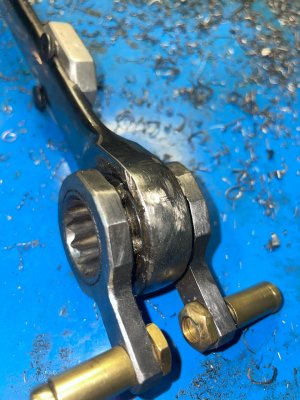
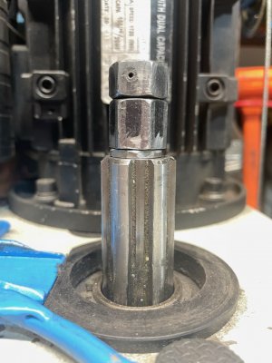
Yup - nasty problem waiting to bite every new mill user. That is what the collar to the left of the big nut in the photo I posted earlier (post #18 above) is for. I install it when needed.

Another thing I have experienced is a shallower than normal drawbar thread depth. The drawbar bottoms out, you think you are good (as in collet seated). Start machining & bad things happen.
PETER!!! I think you just stumbled on a MUCH BETTER EXPLANATION for broken pins! Without adequate drawbar tension on the taper, it could easily spin - an almost certain recipe for a broken alignment pin!
I've just officially changed my mind from inadequate drawbar torque to an arbour that won't allow the drawbar to seat properly!
Advice please - instead of the 1/8” drawbar spacer I’m using (post 67 above, picture below).
Any reason i shouldn’t just shorten the drawbar?
Note: with all my tooling, i have 5/8” to 3/4” of thread engagement; and also the drawbar has double nuts. If i regret shortening the drawbar, i could shorten the long nut.
Thanks
CW
Any reason i shouldn’t just shorten the drawbar?
Note: with all my tooling, i have 5/8” to 3/4” of thread engagement; and also the drawbar has double nuts. If i regret shortening the drawbar, i could shorten the long nut.
Thanks
CW
Attachments
I think it's a lot easier to make new collars and use them as required than it is to make a new draw bar if you mess it up.
The general rule of thumb is that the thread engagement should be 50% longer than (1.5 x) the diameter of the shaft. Depending on the application you might need more or less than that. It's what I use.
The general rule of thumb is that the thread engagement should be 50% longer than (1.5 x) the diameter of the shaft. Depending on the application you might need more or less than that. It's what I use.
This seems like a conservative assumption, but you will not go wrong with using it.I think it's a lot easier to make new collars and use them as required than it is to make a new draw bar if you mess it up.
The general rule of thumb is that the thread engagement should be 50% longer than (1.5 x) the diameter of the shaft. Depending on the application you might need more or less than that. It's what I use.
This seems like a conservative assumption, but you will not go wrong with using it.
The trouble is that the length is not linearly proportional to diameter. That's why I use 1.5. As you say, it is conservative.
If length is critical you can always do the actual math.
Since draw bars are continually set and reset, and there isn't really much downside to a longer thread engagement, it is probably better to use a rule like this.
Failure is likely to start at a thread root and propagate along a sheer plane to an adjacent one. Most of the time, about 3 turns can develop the full strength
Failure is likely to start at a thread root and propagate along a sheer plane to an adjacent one. Most of the time, about 3 turns can develop the full strength