• Scam Alert. Members are reminded to NOT send money to buy anything. Don't buy things remote and have it shipped - go get it yourself, pay in person, and take your equipment with you. Scammers have burned people on this forum. Urgency, secrecy, excuses, selling for friend, newish members, FUD, are RED FLAGS. A video conference call is not adequate assurance. Face to face interactions are required. Please report suspicions to the forum admins. Stay Safe - anyone can get scammed.

Collet questions

I suppose it's worth considering the excessive torque scenario too......
I have, to my shame, put excessive torque on a drawbar. I lengthened it. After loosening it, I could still tap the collet out (more or less) normally. Nothing otherwise bad happened.

Assuming only the larger thread portion of the setscrew actually threads into the spindle, I could try gentle tapping the smallest portion in further so it falls out the bottom, or try to make a tool to reach up through the bottom to push it back from the inside back in the direction it was threaded in from, though that seems near impossible?
If with very gentle taps it doesn't pop out and fall onto you table, then the setscrew still has threads on it. Now you have a problem to solve.

Check by eye (bore scope, mirror, or by direct looking if you are more flexible than I am) and see if the pin intrudes into the bore. You can of course feel it with a collet -- If it doesn't intrude into the spindle, you will have to fabricate a way to turn it - either into the spindle or all the way out. As I recall, the spindle wall is just under an inch of thread at that point. So it is easier to wind it into the spindle than back it out -- unless there is swarf kin the threads. Junk somehow gets into the threads. I don't know how!!! Then you might have to make a drill guide out of a set screw to drill it through the centre , and then progressively larger drills to drill out the piece (very carefully)...

If the 'bad thing' happens you can always go larger, and make your own dog point setscrew. Not standard, but it would work just fine and not hurt the mill. IF you go that way -- you have to relieve the hole on the inside of the spindle - it is really important so you don mess up the collet as it goes in...
 
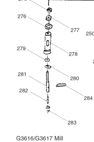
I don't see anything in the Grizzly Tools drawing of my mill with respect to the R8 key.

1700200209580.webp

Literally a hand sketch rather than a proper exploded mechanical drawing.

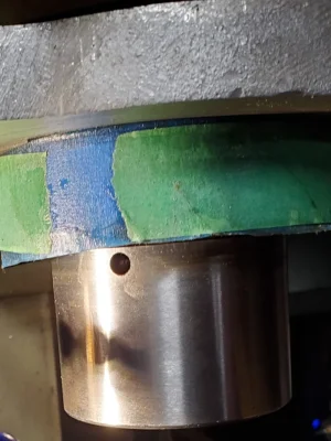
Taking off the bearing dust cover #280 above the hole for the R8 Key screw shows up.
1700201170941.webp

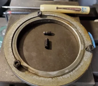
A slotted set screw that wasn't actually tight against the second. The second has a turned down piece that is no longer round. Instead it has two flattened edges. Not sure how that happened. Diameter was about 0.1325 with a length of about 0.1325.
1700201321309.webp

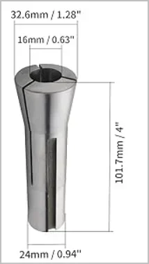
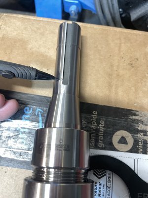
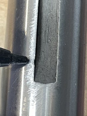
When you look at an R8 holder you'll see that only the top 1.125" or so is precisely ground. Further along it's got a slightly smaller diameter. Inside my spindle the set screw pokes out at more like 1.75" or so. I didn't measure that precisely. It comes out in a roughly finished bore.

In other words the set screw engages below the precisely machined section. The width of the R8 slot is 0.1625 so it's not a close clearance sliding fit with the set screw.

My two cents worth on this subject.
 
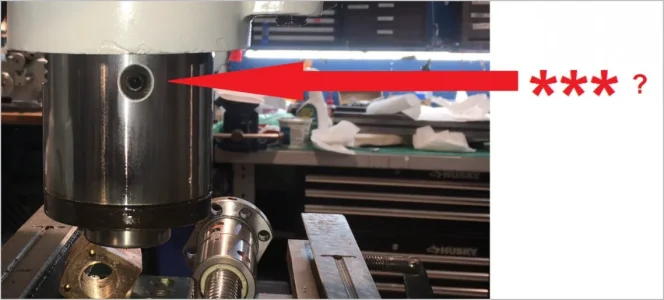
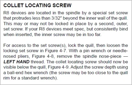
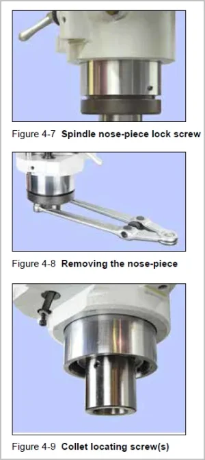
I'm going to guess *** is not the R8 slot set screw but I can't recall off hand what its for because its quite high up in the quill. Confirm with your parts manual but your machine looks generically like the Bridgeport style. If so, there should be a lock screw which retains the bottom nose piece & that screw must first be removed. Then the nosepiece must come off (note thread direction) which exposes the R8 slot set screw(s). That was what I posted earlier showing my ghetto plywood pin wrench. I am attaching excerpt from PM's manual which has some verbiage. Again, your machine may be different, so consult the manual.

1700200759325.png


1700201047475.png

1700201082972.png
 
Last edited:
Oops, I might be a couple posts behind the actual disassembly, sorry about that.
Its hard for me to estimate a length perspective of spindle from the pics. But I want to say my screw is ~1.5" from end of the collet big end? obviously before the slot becomes radiused. But maybe that position varies my machine. Generic dimensions as guide but I have noticed variations in R8 tooling.

1700202430643.webp
 
Oops, I might be a couple posts behind the actual disassembly, sorry about that.
Its hard for me to estimate a length perspective of spindle from the pics. But I want to say my screw is ~1.5" from end of the collet big end? obviously before the slot becomes radiused. But maybe that position varies my machine. Generic dimensions as guide but I have noticed variations in R8 tooling.

View attachment 40467
I went down and measured without getting too anal about it. The set screw hole is 1.75" from the surface of my spindle. The R8 slot extends well past that so there's no issue of running into the curved section.
 
@slow-poke - As far as I know the hole in the spindle isn't such that only the tip of the pin sticks out. The entire pin can be screwed in till it falls out onto the table down the spindle bore. I cant remotely imagine a smaller nose hole. That would require a really long nose on the pin.

It can be a royal pain in the ass to remove. Which is another reason I made mine stronger than normal with a rectangular tip.

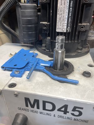
The spindle turns inside the quill so you have to align the two to get at the pin. The two Allen screws (if you have two) might each require a different size Allen key. Another problem I would fix if mine was like that.

There is no way in HELL you would get me to hammer on the pin to get it out. It is prolly just a different size Allen key - or it might be stripped. A stripped key is a HUGE problem that might require a total disassembly. I might try lots of other approaches first, but a hammer isn't one of them.

Here is a link to how it's done on a Bridgeport by H&W Machine repair. My Hartford Bridgeport clone was slightly different. Yours might be too. Be aware that excess torque on the keeper screw can cause the quill to bind.


@whydontu - I searched again for the original patents too and also failed. I can only relate all the conflicting information I found and synthesized for myself back when I dealt with this same issue on my mill.

Like most, I have to believe that the taper does all the torque holding. But something is shearing pins cuz they don't just dissolve. A sheared pin is a bad thing. But an R8 Arbour of any kind spinning in a spindle taper is a MUCH WORSE BAD THING. Hence my desire to improve the pin.
 
Last edited:
If with very gentle taps it doesn't pop out and fall onto you table, then the setscrew still has threads on it. Now you have a problem to solve.

Check by eye (bore scope, mirror, or by direct looking if you are more flexible than I am) and see if the pin intrudes into the bore. You can of course feel it with a collet -- If it doesn't intrude into the spindle, you will have to fabricate a way to turn it - either into the spindle or all the way out. As I recall, the spindle wall is just under an inch of thread at that point. So it is easier to wind it into the spindle than back it out -- unless there is swarf in the threads. Junk somehow gets into the threads. I don't know how!!! Then you might have to make a drill guide out of a set screw to drill it through the centre , and then progressively larger drills to drill out the piece (very carefully)...

It appears as if this did not use a stepped setscrew, appears as if they used a small setscrew that protruded (past tense) into the spindle hole, that was held in place by the M5-0.8 set screw (now removed) and all that is behind the M10 setscrew marked *** in the image above. The inner most setscrew does not appear to have a hex key opening.

The middle setscrew (behind the one marked *** in the image above) is M5-0.8. I drilled a 1/16" hole through the center of a M5 screw this morning. I can start with the 1/16" bit or I can increase the size of the pilot hole up to say 1/8"

A 1/16" bit in a hand drill is pretty fragile, I'm inclined to go up to 1/8" and see if I can drill through what remains of the inner most setscrew. I do have some small easy outs, so with a 1/8" hole I could try and ease it out.

I hope this does not end badly.

Thoughts?

BTW that hole *** is 3" from the bottom of the spindle, and the outer edge of the inner most setscrew (setscrew #3) looks to be about 1/4" from the outer surface of the spindle
 
It appears as if this did not use a stepped setscrew, appears as if they used a small setscrew that protruded (past tense) into the spindle hole, that was held in place by the M5-0.8 set screw (now removed) and all that is behind the M10 setscrew marked *** in the image above. The inner most setscrew does not appear to have a hex key opening.

I advise extreme caution. That whole affair in there is complicated and difficult to diagnose. You might not be looking at what you think you are looking at. It's a bit hard to swallow that the hex socket is buggered.

The middle set screw *** is 3" from the bottom of the spindle, and the outer edge of the inner most setscrew (setscrew #3) looks to be about 1/4" from the outer surface of the spindle

3" seems more than I'd expect.

I misunderstood this whole hammer it out suggestion. Reading @Dabblers post,it seems he is only advocating light raps that assume that the plug has already cleared the threads in the spindle. That's ok. But if it is still held in by threads it will make a mess of the spindle if you hammer it out. Hence my aversion to the hammer.

Regarding using drills and extractors - if it comes down to that, I'd remove the spindle so you can be sure that you are doing it right. I would not risk damaging the spindle. The spindle is the heart and soul of your mill. Removing a stuck plug is child's play once the spindle is out. But taking the spindle out is prolly a lot of work.
 
I'm going to put this on hold, and focus on the CNC conversion. I have no plans to hammer anything, very very gentle tap either it pops out or it gets drilled out
If you think that you still have some thread engagement, try using a left hand drill bit. They will often catch the piece and back it out....... I love me a left hand bit, until sharpening time, that just messes with my mind......:rolleyes:
 
This video shows/discusses some of the issues on the R8 slot set screw & also the retaining screw into the bottom nose cover plate & its potential impact on the its threads.
Keep an eye for relative distance of the screws relative to end of spindle, because I would think most machines are +- similar because they are all using the same collet dimensions.
Your *** screw looks to be in a different position, so I'm scratching my head on that. Maybe its camera perspective or just plain different.

 
I’ve been busy lately and missed this thread. A bit late to the party but this discussion has been quite interested.
In post #18 @Susquatch mentioned my spindle lock out. So I’m gonna try my luck at including a video here about my spindle lock out and also another about my spindle modified ratchet wrench.


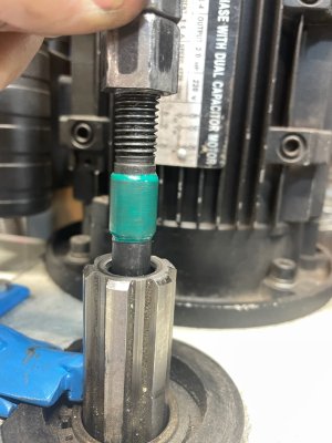
Susq also mentioned his drawbar alignment collar to reduce misalignment and drawbar rattling - he mentioned that one to me a little while ago (thanks) - in the pic below is how i did it since i don’t have a lathe but i do have lots of electrical tape.
C93451AB-7FA5-4A93-8FAA-5AB0EB5FF482.jpeg

Please keep in mind i am not experienced with machining. Actually- I think i have barely graduated from the newbie category. Here a video from one year ago this week. My anniversary of unloading my new mill.


Well - here goes - i hope these are the correct video links and not a politician not answering the question.
 
Last edited:
Darn - that’s the same video of the wrench twice.
Will have to try again with the spindle lock out


PS This is the right one - i was able to edit the above post and deleted the duplicate video
 
Last edited:
Behind it (when I turn the spindle, I see another smaller setscrew, I removed it and it's not stepped like your image. Now that I know where it is, using a mirror I can see that the smallest end piece is broken and flush with the inside of the spindle.
A late thought occurred to me.... The set screw you removed might well be the 'keeper' set screw, and the remainder you see is the dog point set screw. it might be cruddy and messing with your view of the hex socket? Try the same size as the one your removed, it might well beack out. (or if you already tried, well, I'm trying to be helpful)
 
You might also try a blast of canned wind to clean off the head of that last set screw. The long straw does a great job of getting the wind where you need it.

It's ok to assume they are all the same size, but I wouldn't bet my life on it. One time I was helping a neighbour fix a machine that had double set screws. He couldn't get the bottom one out either. After a lot of soaking, wind, and cursing, it slowly became evident that it was slotted. I vividly remember the look on his face when I asked what kind of idiot would do that! I think I stepped on my D&@k that day....
Both mine are slotted right from the factory. The slots are visible when zooming in on the photo I attached. So I don't think that's unusual. Might be because with a slot it's easier to get out.
 
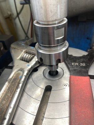
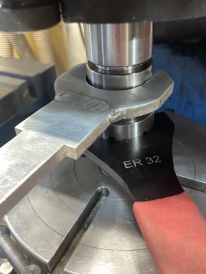
In September I got an ER32 collet set. The only wrench i had to hold the collet holder body while tightening the collet nut was a 12” crescent - very cumbersome. Holding that big crescent and the tang wrench was a handful.
06055EB0-7CAD-4ECA-882D-414E45824CE5.jpeg

EC9A786D-52C5-4388-91F6-6B10C9C1861A.jpeg

I tried using my spindle lock and the tang wrench.
6BB9B8CF-9CC7-4BE3-8BDA-530C166176BD.jpeg

This was putting stress on the R8 set screw. I only did that once. I got very lucky :cool: See pics below
91B834E9-6A76-4F3D-B385-1FD72AFDBBAA.jpeg

8F111C2B-CED9-4845-8A2A-15008350D652.jpeg

Since then I made a much more manageable wrench (aluminum). Haven’t totally finished it yet but it is 100% functional without the cosmetic touchups.
CB3A3F94-4B93-4AEF-B106-14E3A593A245.jpeg

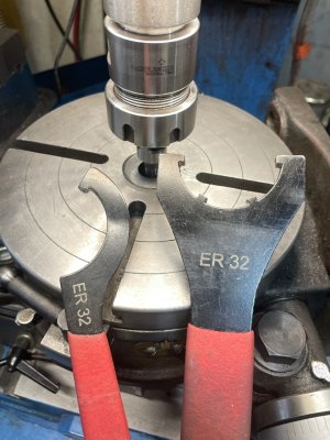
I sprang for the 4 tooth tang wrench on the right (pic below). Big improvement over the smaller one that came with the set.
81AD4651-A085-47D3-BDB2-5631B9693CEC.jpeg
Thanks Susq for that tip.
 
Back
Top