Doggggboy
Ultra Member
Looks like the goodest of boys.One last photo. RIP Grizzles.

Sorry for your loss.
Looks like the goodest of boys.One last photo. RIP Grizzles.


So from the shop, THANKS!!!!
Thank you very much your advise went a long way! Aaaaand you had your chance to input on the colour! hahahahaha😛Awesome job! Loved the story too.
Dunno about that colour though........
you had your chance to input on the colour! hahahahaha😛
i'd say that is a well deserved beer!Well its time for the big reveal!!!! ITS DONE!!!!!!!! (ish)
Over the last few weekends I've managed to put some good time in on completing this mill. I guess I'll try and pick up where I left off.
I took the x lead screw to work and cleaned it up real nice like, installed it on the the table, (after polishing anything I could) and discovered that once again order of operations was imperative. The brass nuts that are used to adjust the backlash in the X Y nut, have to be installed onto the screw separated from each other (DUH, right?). Well guess who didn't do that and spent an hour trying to figure why there was 3 turns of backlash. haha. Once I figured out my silly oversight I got the nuts adjusted to the point where there is ZERO backlash (!!!) and the table does not get tight at ether end. This tells me that the lead screw has almost no wear. This made me very happy.
View attachment 32275
View attachment 32277
View attachment 32281
After this triumph, my ego got checked, by of all things, oil lines.... Those silly little plastic oil lines are a ROYAL PITA!!!!!! If I am ever to do another Bridgeport I will be replacing these with news ones. These ones were hard and reluctant to go into their spots. So lessons.....
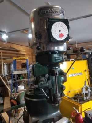
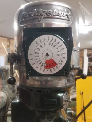
I moved back to working on the head. I installed the adjusting bracket on the forward vari-drive pulley. And then the nice top cover. It's starting to look like something. The motor also went on without a hitch. I took the two bolts out of the motor shaft that were holding the pulley in the full low speed position and with a nice click, there we were. I placed the vari-drive worm and gear assembly on the front (we'll revisit this) and set to work on the electrical... This honestly could be another post. Is anyone interested in my 600V setup?? As for the electrical on the mill, I checked the insulation on the motor when I got it, but I also have gone through and inspected every component and replaced anything that looks arced or burnt. The contactor in the motor starter was questionable so that got tossed to the curb. 600V is still "low voltage", but it should always be treated as if its trying to kill you all the time, like a polar bear, or my wife when I forget to take out the trash on Sunday. The reversing switch was mint so I left that alone and wired everything up. The first motion was getting close!!!
View attachment 32272
View attachment 32279
View attachment 32278
A Before I was too get power happening, I made sure I had good ground continuity from the mill to the panel, and that each phase was independent. I also made sure that I didn't have high resistance anywhere (indicating a poor connection). At this point I was ready to fire it up. Late on a Sunday evening the RPC came to life with a growl, settling into a satisfying buzz. I grabbed my meter and made sure the mill wasn't live, and turned the motor starter on. A little click is all I heard. "Good, no arky sparky" I thought. Once again I made sure that there was no shorts and that the mill was not live (I recommend using the one hand rule with this kind of stuff). Now, I confirmed I was in high gear, and that the down feed was disengaged. With a little trepidation I twisted the direction control to forward and without any hesitation, and a small squeak from the belt, the mill jumped to life. As anti climactic as it was to see an empty spindle turning, it was the culmination of months of work. Satisfying was an understatement. I then proceeded to do the spindle bearing run in. I just kind of went with what I know on that, but imminently I found an issue. The speed control was working in reverse. Easy fix though, pop off the worm gear cover and move the gear to the other side of the stop screw, then wind the chain up the other way. Back in business! I checked the power feed at this point as well. Everything working as it should. After two hours of running in the bearings and some touch up paint where I was clumsy I poured myself a pint and revelled in the new toy. "Now the cheap part is over, time for tooling" I thought.
View attachment 32280
And with this, my mill is complete (minus a fine down feed handle, gotta make one of those), and while I will continue to post any updates or changes made, (like a power draw bar as was suggested... and DRO), I just want to say again thank you all for following along, for the input and suggestions. This forum is fantastic, and helped me stay motivated to do the best I can.
So from the shop, THANKS!!!!
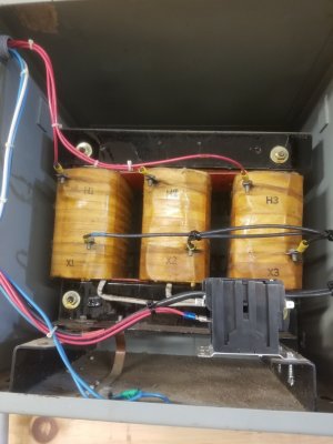
I didn't build this one myself, but it has been heavily modified. I originally had built a 5Hp, 600v RPC (single phase transformer stepping up the 240 to 600 before the RPC, and all controlled by an arduino), but this came up on kijiji and was twice the HP of what I had. So I modified this to run my shop. Now I've got 208, 440 and 575V. I've also got remote on and e-stops planned.@That-Guy great thread! I've been following along and learning from it. You mentioned an RPC. Did you build it yourself?
IMO a separate thread on this RPC journey would be even more interesting!!!I didn't build this one myself, but it has been heavily modified. I originally had built a 5Hp, 600v RPC (single phase transformer stepping up the 240 to 600 before the RPC, and all controlled by an arduino), but this came up on kijiji and was twice the HP of what I had. So I modified this to run my shop. Now I've got 208, 440 and 575V. I've also got remote on and e-stops planned.
How about these options...I got nothin.
.webp")
.webp")
.webp")
.webp")
That would make a beautiful mill! Are you starting on yours?How about these options...
View attachment 50011
Really looks lighter than the first pic... more like below
View attachment 50012
View attachment 50015
View attachment 50014
Actually this is for my chipmaster lathe to start later this summer. Then then down the road we will do the Mill.That would make a beautiful mill! Are you starting on yours?
Yeah it is a sharp looking vehicleI love the Mustang.
That's great!!!Actually this is for my chipmaster lathe to start later this summer. Then then down the road we will do the Mill.
Yeah it is a sharp looking vehicle
Just to let everyone know, I welcome any unsolicited advise on painting with 2 part epoxies. My spray painting experience is limited to rattle cans, small airbrushes and cheap automotive type sprayers on a few occasions. never with any epoxy.That's great!!!
I don't want to give un solicited advice, but I've got a few pointers when it comes to what not to do. I've also got some opinions on primers and paint.... since I've run the gamut from cheap 6$ rattle cans to 500$ a gallon epoxies. If you want any tips just PM me.
Ether way, keep us updated! I want to see more of the Chipmaster!!!
Well in that case... here is a short essay on painting with epoxy.Just to let everyone know, I welcome any unsolicited advise on painting with 2 part epoxies. My spray painting experience is limited to rattle cans, small airbrushes and cheap automotive type sprayers on a few occasions. never with any epoxy.
I do know that a HVLP sprayer is essential. My goal is to media blast all the painted surfaces, fill and sand very smooth, and then use epoxy primer, epoxy automotive paints and then perhaps a clear coat depending on what system I land on, which depends on what products I can get in Canada.
The flat black is for the drip tray, coolant sump, and back splash. IF I could get it in black I'd use a ceramic filled epoxy wear surface, but they seem to be available in blue and red mostly rather than black
Oh yeah, I've done spray foam application and glassing with epoxy, and stone carving which release silica and potentially asbestos. I have environmental sensitivities as well so I know all about PPE. Hell I wear a an N95 (actually a CAN99 mask) every time I leave the house. I also have 3M respirator with a slew of VOC cartridges. But for this and the media blasting I'll be wearing a supplied air respirator, full tyvek suit, booties and nitrile gloves.Well in that case... here is a short essay on painting with epoxy.
Its sucks; first and foremost. lol
The epoxy primer that you use, should be an automotive or an aviation primer. I've used a lot of Sherwin Williams Macro-Poxy, that is amazing stuff (and had silica anti-wear agents in it....FYI), but you almost need to put it on with a trowel its so thick- I leave that for tractors. If you were to go with an automotive 2k or an Azko Noble PC or EC primer, they can flow out nice and if you mix the thinner correctly they are fairly resistant to running. I've used the Eastwood primers to good results, but for the amount your going to need it may be more economical to get an aeronautical epoxy from aircraft spruce in Brantford. I believe they still sell pint kits. With all Epoxy primers there is a dwell time before you start spraying, pay attention to this. Mix it and walk away... don't touch, don't look, don't even think about it. I've messed up a few times spraying in a rush and all you get is a bunch of runs or patchy curing, and a lot of extra work.
Paint is a large subject, and I actually used a lacquer on my mill, but then clear coated with a 2k. There are Sherwin Williams Automotive specialists around that will make any colour you like, but this is a spot where Eastwoods may be your best bet. Their Urethane paints are quite nice, and priced within the realm of reality. Another thing that I've heard you can do, but not tried myself, is get an autobody shop to mix you up some paint. Seems common in the US for old tractor fellas. NAPA also will mix epoxy paints, but you will pay dearly for poor quality paint IMO. One last thing to keep in mind, is clear coat will yellow with heat, exposure to a lot of cutting fluids, and with each passing of the Sun. For that amazing green you've picked, that should not pose an issue, but if for some reason you were going with pearl white, I'd rethink the clear, and go with a good single stage paint.
An HVLP is absolutely not required. I've painted a few aircraft with standard ol' high pressure spray guns and been fine (just more overspray). In fact, for smaller projects (and my mill I did here for that matter) I like the Princess Auto touch up gun, 20$-35$ on sale and toss it at the end of the year or when it just gets too hard to clean anymore. Just remember that with epoxy, it's time and temperature that cures it; so be ready to clean as soon as your done spraying. Another thing I learned the hard way round, is when this stuff gets a bit old, it cures FASTER! I had some set up in the gun while I was at it. had only mixed it 10 mins prior. There are also different curing agents you can get to speed up or slow down the cure, this needs to be matched to the temp your spraying at. Humidity has minimal effect on the primers in my experience, but will haze a gloss paint if its a full on southern Ontarrible August day.
To that point though, PPE is not a option. ALL EPOXY IS TOXIC AS HELL! Supplied air is the gold standard, but a REALLY good respirator (think 3m) with good ventilation is ok. Gloves for sure. The thinner will eat most Nitryl gloves, so have lots ready to swap.
For your drip tray, I like the idea of a ceramic paint, still not sure how well it would hold up in the long run. Keep us posted on that! I might have to start painting mine! If you get down to it and need a bit of guidance or have a question, pm me and I'll send you my number. Or maybe this should be its own thread???