-
Scam Alert. Members are reminded to NOT send money to buy anything. Don't buy things remote and have it shipped - go get it yourself, pay in person, and take your equipment with you. Scammers have burned people on this forum. Urgency, secrecy, excuses, selling for friend, newish members, FUD, are RED FLAGS. A video conference call is not adequate assurance. Face to face interactions are required. Please report suspicions to the forum admins. Stay Safe - anyone can get scammed.
-
Several Regions have held meetups already, but others are being planned or are evaluating the interest. The Calgary Area Meetup is set for Saturday July 12th at 10am. The signup thread is here! Arbutus has also explored interest in a Fraser Valley meetup but it seems members either missed his thread or had other plans. Let him know if you are interested in a meetup later in the year by posting here! Slowpoke is trying to pull together an Ottawa area meetup later this summer. No date has been selected yet, so let him know if you are interested here! We are not aware of any other meetups being planned this year. If you are interested in doing something in your area, let everyone know and make it happen! Meetups are a great way to make new machining friends and get hands on help in your area. Don’t be shy, sign up and come, or plan your own meetup!
You are using an out of date browser. It may not display this or other websites correctly.
You should upgrade or use an alternative browser.
You should upgrade or use an alternative browser.
9" SM Utilathe Restoration
- Thread starter YYCHM
- Start date
Was the motor/pulley vibrating/“walking“ on the bench when you had it running in the picture above? Maybe the rotor on the 3/4 hp motor is out of balance compared to the 1/2 hp motor.
Nope, not walking. Just sitting there humming nice and quiet and smooth.
Tomorrow, I'll check the pulley run out on the 1/2 HP setup and see if it's significantly different than the 3/4 HP setup.
Last edited:
Well... I sat both motors side by side on the bench today and compared them.
The 1/2 HP with a pulley runs way smoother than the 3/4 HP (with the bearings replaced) without a pulley.
Go figure😵
As for pulley runout.
3/4 HP 0.007 radially, 0.023 axially
1/2 HP 0.003 radially, 0.012 axially
The 3/4 HP which had it's shaft reduced from 5/8" to 1/2" shows no shaft radial runout what so ever, so any pulley runout is in the pulley which I sleeved 5/8" to 1/2". That runout is about the same as what it started out as with a good pulley installed.
Guess it's a no brainer, go with the 1/2 HP motor pulley setup.
Just need to decide if I'd ever use reverse and if so source a switch. What's wired onto the original switch and 3/4 HP motor doesn't appear to be color coded, so I'm a little reluctant to mess with it.
Craig
Last edited:
You could always redo the pulley sleeve to make sure the sheaves themselves have no runout. I.E.: do not indicate off the OD of the pulley but rather the belt drive flanks.
Redoing the pulley sleeve is certainly an option. When I dialed in the pulley in the 4J I indicated axially off a sheave flank the belt rides on and radially off the bottom of a sheave V. I guess the belt doesn't actually ride on the bottom of the V.
The bottom line is that the 1/2 HP with a pulley runs smoother than the 3/4 without a pulley. So cleaning up the pulley runout isn't going to negate that fact.
RobinHood
Ultra Member
The bottom line is that the 1/2 HP with a pulley runs smoother than the 3/4 without a pulley. So cleaning up the pulley runout isn't going to negate that fact.
Good point.
Is there a fan on the 3/4 HP motor? Try running it without it to see if there is a difference.
The centrifugal switch is nice and clean?
So when @RobinHood offered up this 6.5” by 1.5”-8 TPI backing plate | Calgary & Canadian Hobby Metal Workers & Machinists
I remembered this FOR SALE: POLAND PUTM 5" 3-JAW CHUCK | Calgary & Canadian Hobby Metal Workers & Machinists
I suspect the jaws on my PRAT 3-J are toast, so here was a chance to own a BISON.

Spent a good portion of today turning the chuck registration on the plate. Over shot the first go and had to start over from scratch😡 Second go was a slow and painful creep up to the required dimension.

The swarf cast iron makes in horrible. What you see in the images is just the tip of the iceberg. I probably vacuumed 5 or 6 times over the course of the entire turning operation. Will probably take an entire day to clean my lathe properly.

Now I need drill mounting bolt holes in the plate. The bolt holes in the chuck are blind so I can't transfer punch their locations onto the plate. Any suggestions before I over think this problem LOL.
Craig
I remembered this FOR SALE: POLAND PUTM 5" 3-JAW CHUCK | Calgary & Canadian Hobby Metal Workers & Machinists
I suspect the jaws on my PRAT 3-J are toast, so here was a chance to own a BISON.
Spent a good portion of today turning the chuck registration on the plate. Over shot the first go and had to start over from scratch😡 Second go was a slow and painful creep up to the required dimension.
The swarf cast iron makes in horrible. What you see in the images is just the tip of the iceberg. I probably vacuumed 5 or 6 times over the course of the entire turning operation. Will probably take an entire day to clean my lathe properly.
Now I need drill mounting bolt holes in the plate. The bolt holes in the chuck are blind so I can't transfer punch their locations onto the plate. Any suggestions before I over think this problem LOL.
Craig
Dig out your Machinery’s Handbook for the formula to calculate the bolt circle diameter.
That didn't help LOL.....
RobinHood
Ultra Member
I can't transfer punch their locations onto the plate
make pins that fit inside the threaded holes nicely (sliding fit, but not sloppy). Turn a point on one end. Make the pins just long enough so you have the point just above the surface. Line up the backing plate and give it a tap. Volà, you have just transferred the bolt hole locations.
RobinHood
Ultra Member
An idea for while you are at it: if you make the register on the backing plate about 10 to 20 thou too small and the mounting holes a little oversized, you can have yourself a “set true” 3J chuck.
Mount the chuck on the plate with the three bolts just snug. Clamp the work piece, indicate it in and “bump” the chuck body to take out any run out. Then tighten the chuck mounting bolts.
Had my import chuck on the 9” Utilathe set up like that. Worked like a charm, especially if I needed to take the work out to check fit. You can always put it back and get it to run true to finish your operation(s) that way.
make pins that fit inside the threaded holes nicely (sliding fit, but not sloppy). Turn a point on one end. Make the pins just long enough so you have the point just above the surface. Line up the backing plate and give it a tap. Volà, you have just transferred the bolt hole locations.
I'm liking this approach. Been sitting here scratching my head as to how to mount the chuck and/or plate on the rotary table.
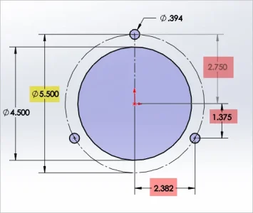
Another option to consider = how I did my adapter plate so it would work for both 3 & 4 hole pattern
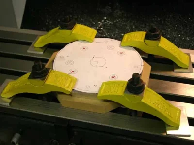
- mount the plate to your mill table (with a drill through sacrifice board underneath like MDF or something)
- dial in on your register boss (or hole if they were turned in same setup)
- probably you can find the bolt diameter for your chuck model number (yellow shade)
- I can generate a drawing like example & then its just easy XY coordinates (red shade)
Attachments
historicalarms
Ultra Member
This will work, I've done the same thing a # of times, even pointed mild steel should mark cast. I have used drill rod, cut to dia. then turn the point then temper, will easily mark steel.I'm liking this approach. Been sitting here scratching my head as to how to mount the chuck and/or plate on the rotary table.
Usually I manufacture one suitable pin is all...insert in one hole & mark & drill, now move pin to the next hole, now insert a bolt into first hole to make sure line-up is accurate to the first hole...cant go wrong.

Maybe once you know the bolt circle diameter, you should be able to use your DRO’s bolt circle function?
If I could get the plate centered under the quill there are a couple of options. I could use the RT or the DRO. Centering is the challenge. I was contemplating turning a 1-1/2" - 8 TPI arbor for that BUT... was that over thinking the problem?
RobinHood
Ultra Member
Use a DTI on an arm held in the spindle and sweep the register that you just turned. Eyeball center the plate first uNader the spindle by lowering the drill chuck into the center bore. Lightly clamp the plate. Then remove the drill chuck and use the DTI. Move the table in X and Y until the DTI reads the same all the way around the register. That equals center under the spindle. Lock off both axis. Clamp down the plate. Recheck for runout. Then use DRO to move to the required bolt hole locations and drill.
If you have never done this - use a piece of scrap wood first to practise.
If you have never done this - use a piece of scrap wood first to practise.
to get the bolt circle:
put in your regular bolts until the thread is stopped.
measure outside to outside on the bolts measuring all 3 spaces
-this will check that they are evenly spaced.
take the average measurement and subtract the bolt diameter.
plug the number into:
diameter = 2/3 * sqrt(3) * [centre-to-centre]
put in your regular bolts until the thread is stopped.
measure outside to outside on the bolts measuring all 3 spaces
-this will check that they are evenly spaced.
take the average measurement and subtract the bolt diameter.
plug the number into:
diameter = 2/3 * sqrt(3) * [centre-to-centre]