• Scam Alert. Members are reminded to NOT send money to buy anything. Don't buy things remote and have it shipped - go get it yourself, pay in person, and take your equipment with you. Scammers have burned people on this forum. Urgency, secrecy, excuses, selling for friend, newish members, FUD, are RED FLAGS. A video conference call is not adequate assurance. Face to face interactions are required. Please report suspicions to the forum admins. Stay Safe - anyone can get scammed.
  • The 2026 Calgary Area Meetup is set for Saturday May 30th at 10am. The signup thread is here! Robinhood has graciously offered to host the meetup again this year. Please note that you MUST RSVP to the notice linked above if you wish to come.

3D Printer Happened

This is great post that you have made as it brings forward capabilities and short falls. The need is diverse, for some printing something that someone else has accomplished is a goal completed. I learned a great deal when I converted my TOS FN20 to CNC, it can hold .001" tolerances, but to make the file of what to machine is complicated, time consuming and frustrating. That was 2013, along comes 3D printing, it can make just about anything, but not what I want to make. Is it a bonus, yes for some, but for others it presents complication that is beyond frustration. As you and others have read my posts in response they seem negative. I don't want to be negative, I want to succeed without losing sleep and being consumed by a system that requires that kind of dedication. I want to draw a part in less than 1 hour, then be able to make a file to print and or machine the part from a plastic filament or a block of material. I am asking a lot. Yet if there is a method of making this all happen I am listening. Looking on the internet, a 3D scanner is on the low end $700 on the high end $10,000. I am hoping for less than $3000 with software that allows me to modify and adjust for part distortion, cracks and time related punishment.

I want people to think for just a moment. If you were to purchase a lathe or a milling machine that could only produce limited parts would you buy it? The limitation is not a file but lays in the hands and mind of the person working the screws. It has no limitation other than the imagination of the person that has access to the lathe or mill or what ever. I want to get into 3D printing, but what I am not interested in is limitation. I want to get past that part and from what I have been reading, a printer is like a lathe tool, it can do a lot but it needs a machine to be more and to be effective. It is not a package, it is dream that can function, but it needs more to be a package. I want a 3D printer to be like my lathe and milling machine... limitless.


TonyK.

Grimsby Ontario Canada.
 
@TonyK
To me all my machines; manual lathe, CNC mill, CNC router, CNC plasma cutter, laser engraver, 3D printer, TIG and MIG welders are only limited by my skills and abilities. Be they design limits for the CNC or techniques on the manual lathe and TIG welder.

From my perspective 3D printing has two major facets; one is the printer and the other what it prints. Printers have evolved to the point where they are quite literally plug and play. My Anycubic Kobra S1 has required zero maintenance from the day it arrived some 900 print hrs ago. It is a reliable as a hammer. It just works. Contrast that to my Ender 3v2 which required incantations to the gods every time I wanted to print.

As far as what it prints that is up to you. Depending on your needs you might never have to design anything. But being that you're a member of this forum I suspect you like to make custom things. And therein lies the rub. If I need some printed item to fit a drawer, or hold an uncommon tool then it's on me to design it so it fits my needs.

I look at it as a challenge to stretch my abilities and learn the skills so that I have the greater abilities to make the things I want/need.
 
I will copy what A.I. has to say about my needs as follows.

A.I. tends to be a bit wordy.


Let us start with the Fiat X1/9 2 hand latch body in the drivers pillar. The handles are metal, but the body of the latch is plastic. As for scanner hardware/software $3000 CND. I have only worked with Cam Bam for my CNC converted milling machine TOS FN20.


The driver’s pillar targa hand latch body for a 1979–1989 Fiat X1/9 is a classic engineering challenge. The original factory part is made from injection-molded plastic with a matte, somewhat textured, dark finish. Over 40 years, it absorbs stress from slamming the targa handles, leading to micro-fractures, warped mounting faces, and oblong screw paths.
Your budget of $3,000 CAD is the perfect "sweet spot." It completely moves you out of low-end consumer toys and lets you buy a true metrology-grade, multi-line blue laser setup. Because you already understand toolpaths, coordinates, and CAD/CAM logic via CamBam, you are already past the hardest part of the learning curve.


Hardware Pick: The 3D Scanner
With $3,000 CAD available, you can afford a scanner that bypasses messy scanning sprays and tracks details down to \(0.02\text{ mm}\). [1]
  • Creality Raptor Pro 3D Scanner
    • Why it works for the Fiat Latch: It packs 22 crossing blue laser lines. Blue lasers do not get "lost" on dark, oily automotive plastics like infrared structured light does. The cross-lines allow it to capture the deep, narrow structural cavities inside the hollow latch housing where the metal handle hinges pivot.
    • The Deal: It retails for about $2,699 CAD, but you can find it directly on the Creality CA Store for $1,973.06 CAD using the promo code CRCA06. This leaves you over $1,000 CAD under budget to allocate toward software or a heavy-duty 3D printer. [1]
  • Alternative Option — Revopoint MetroX Pro 3D Scanner
    • Why it works for the Fiat Latch: This scanner features 30 blue laser lines and hits a single-frame precision of \(0.01\text{ mm}\). It comes with a dual-axis automatic turntable. You can place the unbolted Fiat latch on the turntable, click start, and walk away while it automatically builds a highly precise \(360^{\circ }\) mesh of the part.
    • The Deal: Available directly from Revopoint for $1,493 CAD (discounted from $1,659 CAD). [1, 2]
      1. The Scan Utility (Free with hardware): You will use the software bundled with your scanner (like Revo Scan or Creality Scan) to capture the point cloud, align the top and bottom perspectives, and output a clean .STL or .OBJ mesh file. [1, 2]
      2. The Parametric CAD Tool (Where the magic happens): You need to import that .STL into a parametric program like Autodesk Fusion 360 (which has a free hobbyist tier) or Shapr3D.
        • The Process: Instead of trying to "edit" the messy mesh, you use it as a 3D reference skeleton. You will generate flat reference planes across the latch's mounting face, project sketches onto those planes, and use your machining logic to sketch perfect geometric circles over the worn-out screw holes. You then extrude those sketches to build a brand new, mathematically flawless solid body. [1, 2]


    • Manufacturing an "Equivalent" Latch
      To ensure the printed latch body holds up to the mechanical force of the metal handle without snapping or degrading, prioritize the following choices:
      • The Material: Do not use PLA or standard PETG. Use ASA (Acrylonitrile Styrene Acrylate) filament. ASA matches the factory semi-matte black look of 1980s Fiat plastics, resists temperatures up to \(100^{\circ}\text{C}\) inside a hot car cabin, and is highly UV-resistant so it won't bleach or rot in the sun.
      • The Print Orientation: The latch body will experience shear stress when you pull the handle to release the targa roof. 3D prints are weakest along the horizontal layer lines. Orient the part on your printer's build plate so that the structural mounting ears are printed flat, ensuring the layer lines run parallel to the direction of force.
    • Would you like to focus on finding a 3D printer capable of handling engineering filaments like ASA within your remaining budget, or should we look at the specific PC system requirements needed to run these blue laser scanners


    • Answer this. Would it be possible now to take this scanned file and generate a G code file to produce this part from a solid block of Aluminum on my TOS FN20?


      Yes, it is absolutely possible to machine this latch from a solid block of aluminum on your converted TOS FN20 using your existing CamBam setup. [1]
      Because an original injection-molded plastic part relies on thin walls and wide, hollow cavities, milling it out of a 6061 aluminum block means you will be upgrading your Fiat X1/9 to a highly durable, "indestructible" component.
      However, you cannot just drop the raw 3D scan mesh straight into CamBam and click generate. You will need to approach this with a machinist’s mindset through a specific digital-to-physical workflow. [1]


      The Machining Workflow

      1. Mesh to Solid Body (The CAD Phase)
      A raw 3D scan is just a "cloud" of millions of triangles. If you try to run toolpaths directly on a raw scan mesh, your tool will constantly chatter and dive trying to trace every microscopic surface wrinkle or piece of dust. [1, 2]
      • The Action: Import the .STL scan file into software like Autodesk Fusion or FreeCAD.
      • The Strategy: Use the scan as a visual template. Re-sketch the latch body using clean, perfectly smooth parametric geometry. Make the mating surfaces perfectly flat, make the pin hinges true cylinders, and export this as a clean STEP or IGES file. [1, 2, 3, 4, 5]
      • 2. Import to CamBam (The CAM Phase)
        CamBam handles 3D solid profiles quite well via its 3D Surface machining operations. [1]
        • The Action: Drop your clean STEP/IGES model into CamBam.
        • The Strategy: Set up a 3D Profile Roughing operation with a larger endmill to hog out the bulk of the aluminum, followed by a 3D Profile Finishing pass using a ball-nose endmill to smoothly curve the organic exterior shapes of the latch pillar housing. [1]

      • 3. Post-Process to G-code
        Once the toolpaths look clean in CamBam's simulator, right-click the machining operations to Produce G-code (.nc or .tap file) tuned specifically to whatever controller you used to convert your TOS FN20 (e.g., Mach3, LinuxCNC, or Centroid). [1, 2, 3, 4, 5]


        Critical Machinist "Gotchas" for This Specific Part
        When moving from a plastic injection-molded design to an aluminum milled design, you must modify your CAD file to suit a milling cutter:
        • Mind the Internal Corners (The Radius Pitfall): The factory plastic latch will likely have sharp internal corners where the walls meet. A spinning endmill cannot cut a perfect \(90^{\circ }\) sharp inside corner; it always leaves a radius equal to the radius of the cutter. You must alter the CAD model to add small corner reliefs (dog-bones) or design internal radiuses that accommodate your smallest ball-nose or flat endmill.
      • Two-Sided Machining (The Flip Setup): The targa latch has functional features on both sides—the outer aesthetic face that fits against the driver's pillar, and the hollowed-out back side that houses the latching mechanism. You will need a two-operation setup. You will cut side A, machine custom soft-jaws on your vise to securely hold those newly milled aluminum curves, flip the part over, and machine side B.
      • TOS FN20 Travel Constraints: The compact toolroom footprint of the TOS FN20—with roughly 300 mm of X-travel and 170–200 mm of Y-travel—is a massive advantage here. Because the latch is relatively small, it will easily fit into a standard milling vise, allowing you to maximize the machine's rigid frame for a great surface finish. [1, 2, 3]

    • I then asked the following.
  • Would the Bamboo printer be able to make this part once scanned?


    Yes, a Bambu Lab printer can absolutely make this part. In fact, it is widely considered the best prosumer tool on the market for this exact job. [1, 2, 3]
    Bambu Lab printers—specifically the Bambu Lab P1S and the flagship Bambu Lab X1-Carbon—are designed with full enclosures. This enclosure is critical because it traps ambient heat, which is required to successfully print ASA (Acrylonitrile Styrene Acrylate) filament without it warping, shrinking, or cracking off the build plate. [1, 2, 3, 4, 5]


    Why Bambu Lab Fits This Automotive Project
    • Engineering Material Ready: The P1S and X1-Carbon come with all-metal hotends capable of reaching 300°C and heated beds that reach 100°C. This allows you to print factory-equivalent, high-impact, UV-stable automotive plastics natively. [1, 2, 3, 4]
    • The Slicer Workflow (Bambu Studio): Bambu Lab’s free software, Bambu Studio, seamlessly imports the .STL or .STEP file you generate from your 3D scanner. [1, 2, 3, 4]
    • Automatic Calibration: These printers automatically calibrate their vibration, pressure advance, and first-layer height. For a machinist used to dial indicators and tramming a mill, this means you get automated, reliable precision without endlessly tweaking the printer. [1, 2, 3, 4]


    Which Bambu Lab Model to Choose?
    Depending on how you want to allocate the remaining balance of your $3,000 CAD budget (after buying your ~$1,973 CAD blue laser scanner), you have two ideal

  • Bambu Lab P1S
    Bambu Lab P1S
    $499.00$899
    Bambu Lab CA& more
    4.8
    (2.4K)

    • Why it fits: It is fully enclosed and features the exact same high-speed motion system as their top-tier printer. It will print an ASA Fiat latch body flawlessly.
    • Deal: Available directly from the Bambu Lab Global Shop for approximately $949 CAD. Combined with your scanner, this keeps you right around your total $3,000 CAD target. [1, 2]


    Bambu Lab X1-Carbon
    Bambu Lab X1-Carbon
    $1,869.00
    Bambu Lab CA& more
    4.8
    (358)
    • Why it fits: It adds a hardened steel nozzle out-of-the-box (allowing you to print abrasive, bulletproof Carbon Fiber-reinforced Nylon for high-stress structural parts) and a Lidar sensor that automatically inspects the first layer for microscopic flaws.
    • Deal: Retails for approximately $1,599 CAD on the Bambu Lab Store. [1, 2]


    • TonyK

    • Grimsby Ontario Canada
 
Last edited:
@jcdammeyer
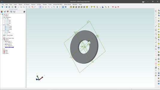
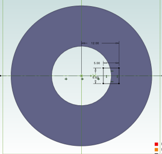
I drew the two circles, added the square but I dimensioned it to be 2mm from the horizontal line, achieving the same thing as the symmetrical constraint.

Trimmed off the bits of the square that were hanging out in the bore and extruded it.
View attachment 84300

View attachment 84299
Now make it 45mm diameter with a 19mm hole and 5mm square key.

I changed the OD to 45, ID to 19 and changed the 4mm dimension to 5mm. The other side of the key was based on the first so everything was easy to scale.
1783904685951.png
For the first 10 years or so of using Alibre I had no idea what to do with parameters. Now I try my best to do it all that way.
 
Now make it 45mm diameter with a 19mm hole and 5mm square key.

I changed the OD to 45, ID to 19 and changed the 4mm dimension to 5mm. The other side of the key was based on the first so everything was easy to scale.
View attachment 84303
For the first 10 years or so of using Alibre I had no idea what to do with parameters. Now I try my best to do it all that way.
I do need to learn how to use parameters.
 
For CAD I have been using my ancient 32 bit version of AUTOCAD 2000 Education Edition and learning Onshape. It does work in the 64 bit environment fairly well, not perfectly. There are times I use Autocad because I can get it done fast and other times I use Onshape to expand my capabilities there. The old Autocad is lacking many items that were not thought of at the time it was released and the new versions that I can use at work are stupidly complex in areas that it should not be.
Pierre
 
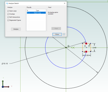
Notice the highlighted blue circle on the RHS.

You lost me here. No blue circle.

I could do the washer pretty easy in Fusion. The keyway would have me staring at the screen and wanting some whiskey - I don't drink.

Everything you said about the Keyway after that was Greek. I think you meant restraint not constraint. As in "Exercise some restraint and don't punch the video screen".

I drew the two circles, added the square but I dimensioned it to be 2mm from the horizontal line, achieving the same thing as the symmetrical constraint.

Trimmed off the bits of the square that were hanging out in the bore and extruded it.

This makes a bit more sense.

But why do you need to trim something that isn't there? Didn't you take a square chunk out of the washer? Why isn't it just a square eraser? Can't you just choose draw, erase, trim, chamfer, colour, etc, then what shape, then where, etc etc?
 
I do need to learn how to use parameters.
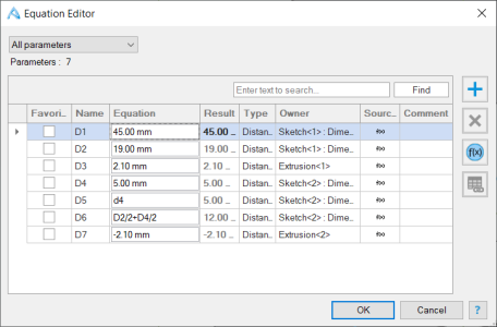
While editing a sketch click on the dimension.
1783906829279.png
Then click on the f(x) button.
Here are the parameters
1783906853565.png

D1 and D2 are the OD and ID. D3 is the Extrude Boss value to make the washer 2.1mm thick.
The D4 represents the thickness of the key slot in the X direction. Since it's a square key the Y direction is the same so instead of choosing 5.0mm it's easier to use D4.

And that's why I used the constraint to put the two horizontal lines to be symmetrical about the X axis. A distance to a line is now not needed. Although you could also use D4/2=2.5mm above the X axis instead of the symmetrical feature.

Finally the depth of the keyway is based on the two dimensions so change one of the main dimensions and the position of the keyway changes.

If I wanted a 6mm key I can edit it in the Equation editor to be say 6mm and now the broach will need to be 6mm instead of 5mm to cut the keyway.
 
@DavidR8 and @jcdammeyer ....... you two can just quit it now, I know what you're up to...... trying to make it look easy enough for a nine thumbed man like me..... well, it's not going to work, I am too poor to lift my balls off the fence rail, although debt always used to be enough of a motivator to get me to work from time to time. 🙄
I am so tempted, it's the programming it myself that scares me into thinking it will sit unused too much of the time..... decisions, decisions ....😳
 
You lost me here. No blue circle.

I could do the washer pretty easy in Fusion. The keyway would have me staring at the screen and wanting some whiskey - I don't drink.

Everything you said about the Keyway after that was Greek. I think you meant restraint not constraint. As in "Exercise some restraint and don't punch the video screen".


This makes a bit more sense.

But why do you need to trim something that isn't there? Didn't you take a square chunk out of the washer? Why isn't it just a square eraser? Can't you just choose draw, erase, trim, chamfer, colour, etc, then what shape, then where, etc etc?
It's a different way of thinking. All the Parametric CAD systems use similar ways of doing this.

With respect to the blue circle the problem was the screen shot didn't show up on the posting. I had to back track and recreate the screen shot and edit it in.

The reason @DavidR8 had to take it out is because these drawings can't have open loops or odd lines hidden by others. Something to do with rendering them in the future or even creating 3D print files.

1783907803741.png

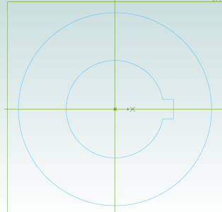
So to not have this error you have to do remove the square on the inside.

1783907890230.png
Now this can be extruded up into whatever thickness you want.

But when you talk about erasing it's done the way I did which is draw a square on top of the disk and then used the extrude cut in the negative direction to remove the material. That's parameter D7 in that above screen shot.
1783908161001.png
Now I could have also set that parameter to be -D3 instead of -2.1mm. It all depends on whether the keyway is always all the way through.
 
@DavidR8 and @jcdammeyer ....... you two can just quit it now, I know what you're up to...... trying to make it look easy enough for a nine thumbed man like me..... well, it's not going to work, I am too poor to lift my balls off the fence rail, although debt always used to be enough of a motivator to get me to work from time to time. 🙄
I am so tempted, it's the programming it myself that scares me into thinking it will sit unused too much of the time..... decisions, decisions ....😳
Just following the forum rules of behaviour.... (to get you to spend money....)
 
@DavidR8 and @jcdammeyer ....... you two can just quit it now, I know what you're up to...... trying to make it look easy enough for a nine thumbed man like me..... well, it's not going to work, I am too poor to lift my balls off the fence rail, although debt always used to be enough of a motivator to get me to work from time to time. 🙄
I am so tempted, it's the programming it myself that scares me into thinking it will sit unused too much of the time..... decisions, decisions ....😳
You know you wanna....
 
That's the bloody problem. 🙄
I even found the file to print the choke lever for one of my chainsaws. That takes almost $40 off the printer price right there....... seems like it should justify spending a thou or so......😛
Here's the thing. I paid good money for a 3:1 tool for shearing, bending and rolling metal. Also a corner notcher and the 3T press hopefully for punching holes. All to be able to make boxes for projects etc.

My first 3D printer was a nozzle mounted in place of the router on the CNC router printing on a glass plate. However, unheated glass just didn't work. A few friends had bought a cheap one ($255 including shipping from Hong Kong) so I took the plunge and had it for many many years.

I rarely make anything out of sheet metal anymore. Just no point when there's a 3D printer and CAD. And I agree 100% with @YYCHM that after the initial fun of making other peoples designs CAD is pretty important.

But remember there are lots of design out there for stuff to help organize etc. too. You'd be printing for hours. A decorative flower pot for pennies compared to buying one. And the list is huge.

In some ways it's the 'hammer principal'. When all you have is a hammer everything looks like a nail.
 
My take on getting a 3D Printer. Unless your willing to bull your way though the CAD learning curve, don't bother. I have found very little on-line that's useful to me.

Please define useful.....

Did you look for a bedside table holder for your teeth?

How about a TV Remote stand?

A toilet paper dispenser?

A tablet/phone stand for the shop?

A flower vase for one rose to say I'm sorry with?

A pocket pill box for your valium?

Bolt sorter with posts to identify nuts and holes for screws?

Tell us what your last home rant was. After we laugh at you, maybe we can help you avoid another one.
 
Back
Top