-
Scam Alert. Members are reminded to NOT send money to buy anything. Don't buy things remote and have it shipped - go get it yourself, pay in person, and take your equipment with you. Scammers have burned people on this forum. Urgency, secrecy, excuses, selling for friend, newish members, FUD, are RED FLAGS. A video conference call is not adequate assurance. Face to face interactions are required. Please report suspicions to the forum admins. Stay Safe - anyone can get scammed.
-
Several Regions have held meetups already, but others are being planned or are evaluating the interest. The Calgary Area Meetup is set for Saturday July 12th at 10am. The signup thread is here! Arbutus has also explored interest in a Fraser Valley meetup but it seems members either missed his thread or had other plans. Let him know if you are interested in a meetup later in the year by posting here! Slowpoke is trying to pull together an Ottawa area meetup later this summer. No date has been selected yet, so let him know if you are interested here! We are not aware of any other meetups being planned this year. If you are interested in doing something in your area, let everyone know and make it happen! Meetups are a great way to make new machining friends and get hands on help in your area. Don’t be shy, sign up and come, or plan your own meetup!
You are using an out of date browser. It may not display this or other websites correctly.
You should upgrade or use an alternative browser.
You should upgrade or use an alternative browser.
2x72 sander
- Thread starter ShawnR
- Start date
I've been thinking a lot about this over the past few weeks.
That is good.
--are two sets of plans all ready available and affordable. Phil Vandelay's, which is less intricate, and more for a machinist, and Jeremy Schmidt's, which needs a lot of welding, but is more versatile. They both tilt, but it is easy to edit that part out of the plans.
There are several plans available. The ones I have been leaning towards are the revolution model
https://www.etsy.com/ca/listing/767...-set-of?ref=landingpage_similar_listing_top-2
All have features that are appealing to to us, depending on what we want I guess. I feel Vandelay's model is complicated to build ie lots of parts and Schmidts model seems finicky with the welding of the bar stock to fit the tube and for me, I did not have convenient flat stock to work with. I, so far, ( ie not committed yet to much) have the sliding parts working so now just onto structure. Yes, the 48" models would be much easier and in hindsight, might have been a good way to go. A wannabe knife maker pointed me towards the 2x72 Schmidt version, and I fell into the rabbit hole (as I am prone to do) so here I am. There are lots of great plans out there. I, originally, when I started this thread, was hoping to develop a set of plans that we could post as our own but it looks like this will just become a build thread. At least we have all had some good input. For future visitors, hopefully, they can gain from it.
Thanks
Cheers
Cleaned up the last of my aluminum castings today. Some are good, some look a little roughish but I think they will all work. Need to decide what size wheels I want.
@Crosche any suggestions? Does different size wheels at the top and bottom of the platen make sense for having the versatility to rotate the platen for different size radius? Or does that bring other issues? I am wondering about maintaining belt tension. Would have to plan that out carefully with dimensions.
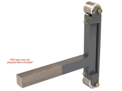
I was thinking of doing my platen like the one shown below. I like the idea of the wheels being supported on both sides though and have 1x2" material so it should be easy enough. I think it would be more rigid than a one sided axle for the wheels. Most platens that I have seen are made of 1/2" plate.
Attachments
Last edited:
Cleaned up the last of my aluminum castings today. Some are good, some look a little roughish but I think they will all work. Need to decide what size wheels I want.
@Crosche any suggestions? Does different size wheels at the top and bottom of the platen make sense for having the versatility to rotate the platen for different size radius? Or does that bring other issues? I am wondering about maintaining belt tension. Would have to plan that out carefully with dimensions.
I was thinking of doing my platen like the one shown below. I like the idea of the wheels being supported on both sides though and have 1x2" material so it should be easy enough. I think it would be more rigid than a one sided axle for the wheels. Most platens that I have seen are made of 1/2" plate.
The different wheel sizes are nice to have, but I would only do that if the wheels are rubber coated; bare aluminum isn't great to grind hard materials on so you probably won't use them much. Stick to the same diameter wheels if your wheels are bare aluminum, because it will simplify your build. Also, I would reconsider building an adjustable platen. Please see attached photos of my platens.
Nice castings BTW.
Attachments
The different wheel sizes are nice to have, but I would only do that if the wheels are rubber coated; bare aluminum isn't great to grind hard materials on so you probably won't use them much. Stick to the same diameter wheels if your wheels are bare a
Nice castings BTW.
Thanks Chad. That is a heavy duty sander! I am going to look at options today and decide what direction to go in. And will go with the same size wheels.
Cheers,
Couldn’t you make a slide/press on plastic or rubber that would slide onto the axle?
You would have a good assortment from gas line to water line available.
Probably...depending on what one has access to. I have no idea what will be wanted yet with it but I like your idea....adds options.
@Crosche what size shafts do the platen bearings use? Would half inch be heavy enough? I might make the wheels next. I have the base plate and vertical components cut but then bogged down with other projects. I keep moving the chunks of aluminum around my bench so might as well make them into something useful. I can order the bearings for them too once I know what size shaft I should be using. I am considering a 2 sided support too so I guess in that instance, half inch would be lots but I am wondering what the one sided platens use for bearing supports. I don't know what kind of tension gets applied to the belt.
Started putting some stuff together today. I have been trying to come up with a drawing in FreeCAD before I put stuff together but losing too much time so I decided to just go at it. But then..... realized that it would be nice to be able to have an idea of where to put parts and how long to make them so back to FreeCAD... but only to layout things out 2 dimensionally. I don't have my head around planes exactly yet so positioning parts forward and aft has me a little puzzled. But I was able to get what I needed, and that is practical lengths for the components. The only actual metal stuck together right now is the two posts and the flat plate bottom. If anyone wants to have my FreeCAD drawing to load into their FreeCAD to practice with or play with, I can email it but can't upload it here so just a pdf for now.
Attachments
Post it in a zip file.
mmmm...learn something new everyday.....
Thanks!
Attachments
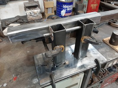
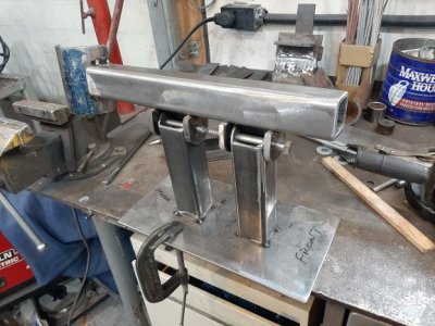
Little more progress....
Disregard the "Front" and "Motor" designations . Plate is symmetrical and I just needed to work on this side. I had some old pipe that fit the motor diameter so it formed my motor mount.
Disregard the "Front" and "Motor" designations . Plate is symmetrical and I just needed to work on this side. I had some old pipe that fit the motor diameter so it formed my motor mount.
Attachments
Last edited:
@YYCHM 72" is because of the popularity of some very expensive knifemaking grinders in the 80s. .
Dabbler, curious see what these look like - any particular brand names?
Shawn, I'm watching the build...thanks for posting it all. Did you get the drawings from Jeremy Schmidt as a precendent or entirely your own design?
I've decided I want one of these but am waivering on what to build - the tug on war making the the perfect swiss army knive version that is does everything....or just getting on with something simple. I do see the benefit of tilting, quick and easy belt changes....maybe a tilting table as well as something that is very solid and smooth running. Is variable speed much of a desirable feature? why - more control over the removal rate or some such thing?
Last edited:
Dabbler, curious see what these look like - any particular brand names?
Shawn, I'm watching the build...did you get the drawings from Jeremy Schmidt as a precendent or entirely your own design?
I've decided I want one of these but am waivering on what to build - the tug on war making the the perfect swiss army knive version that is does everything....or just getting on with something simple. I do see the benefit of tilting, quick and easy belt changes....maybe a tilting table as well as something that is very solid and smooth running. Is variable speed much of a desirable feature? why - more control over the removal rate or some such thing?
Slow build...getting distracted and trying to learn FreeCAD along the way. Spending too much time in front of the computer and not enough time making chips.....so be patient....
I do have Jeremy's plans that a friend purchased but not using them. I do refer to the Revolution model ( link below) but just from photos from the websites, no plans. So mine will be kind of based around that.
I also received plans from a member here so am referring to them a bit too.
Yes, my personal requirements are tilting belt and tilting, independant table. I am working on the platen now, using a 1x2x10" tube instead of one sided half inch plate. Mostly because I have lots of 1x2 and not much of 1/2" plate. I also think the bearings would be better supported by being supported on both sides but honestly, most of the belt sanders out there use one side support with a half inch shoulder bolt. Sometimes I have to swim up stream...
I also want variable speed. I think it would be important and I have several treadmill motors with controllers so that aspect is pretty easy for me. Why not?
But, I have no experience with them so really fumbling along. @Crosche , as you would of seen, has been giving me good input since he has and uses one.
Thanks for hopping in.
Cheers,
https://www.etsy.com/ca/listing/767...XE-zw_uMZDYrJiPqyICIs0KfEhPswIkhoCWLMQAvD_BwE
Dabbler, curious see what these look like - any particular brand names?
I don't remember any brand names, probably out of business by now. I know of one in Airdrie, but I haven't heard from the owner in 5 or so years. Sorry I can't help with exact information, but arrangement of the pulleys is similar to all the designs out now. they ranged from 2000$ to 3000$ back then...
Dabbler, curious see what these look like - any particular brand names?
Shawn, I'm watching the build...thanks for posting it all. Did you get the drawings from Jeremy Schmidt as a precendent or entirely your own design?
I've decided I want one of these but am waivering on what to build - the tug on war making the the perfect swiss army knive version that is does everything....or just getting on with something simple. I do see the benefit of tilting, quick and easy belt changes....maybe a tilting table as well as something that is very solid and smooth running. Is variable speed much of a desirable feature? why - more control over the removal rate or some such thing?
Have a look at Nexus Grinders from Lethbridge.
I don't remember any brand names, probably out of business by now. I know of one in Airdrie, but I haven't heard from the owner in 5 or so years. Sorry I can't help with exact information, but arrangement of the pulleys is similar to all the designs out now. they ranged from 2000$ to 3000$ back then...
I've seen ones where you can change the front of them, basically switch from a flat platen to largish diameter wheel. I wonder if that's the style you thinking of? I can see how the large wheel would be useful for someone making a knife, i.e. to get the hollow grind...not sure I'd ever use it. Doesn't matter, was just thinking that having a look the rolls royce might spruce up the chev
There's also a bunch of drawings and ideas on grab cad (free)
You could always build the chassis for the grinder and buy the accessories; that will probably save you the most money with the least amount of time invested in the build.
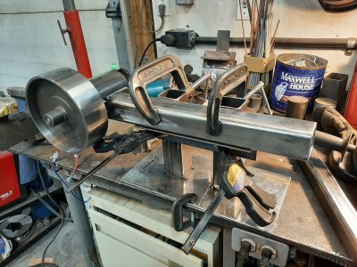
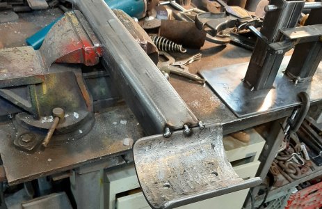
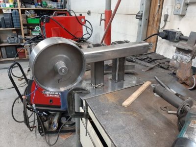
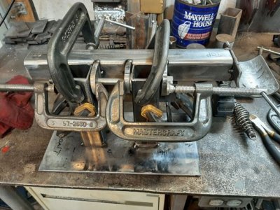
Good progress today. Made the axle for the rotating motor assembly. Just a half " rod with threads at either end. Still fascinating to be able to cut threads on a lathe. I have little goals in life....
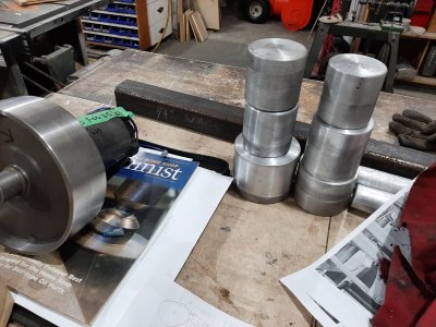
Then fitting up of the pivots for the main motor mount. In the revolution plans, and many others, there is a receiver below the main bar (aka top bar, rotating motor assembly...) for attaching a rest/table of some sort. I did not commit to it yet but looks like I am going that way, after being able to rotate the main bar today, I was trying to figure out another way of doing it but that looks best. Another example of either "don't reinvent the wheel" or "most plans have it that way for a reason". But regardless, good progress today. Some work on the platen too. Bearings for wheels are due this weekend so should be able to make them up. I actually am torn between getting this project done and saving the wheel making for the new lathe so I had a good project for it. But will plunge on with this one.
Then fitting up of the pivots for the main motor mount. In the revolution plans, and many others, there is a receiver below the main bar (aka top bar, rotating motor assembly...) for attaching a rest/table of some sort. I did not commit to it yet but looks like I am going that way, after being able to rotate the main bar today, I was trying to figure out another way of doing it but that looks best. Another example of either "don't reinvent the wheel" or "most plans have it that way for a reason". But regardless, good progress today. Some work on the platen too. Bearings for wheels are due this weekend so should be able to make them up. I actually am torn between getting this project done and saving the wheel making for the new lathe so I had a good project for it. But will plunge on with this one.
Attachments
@Mcgyver a couple that look interesting....not plans though, although the vashti looks like a kit. I did not spend much time on the website
https://vashtigrinders.com/products/rift-2x72-belt-grinder-package
https://reederproducts.com/
https://vashtigrinders.com/products/rift-2x72-belt-grinder-package
https://reederproducts.com/

![20210325_204626[1].jpg](/data/attachments/21/21590-e8901c5797c010bc54a8d4ffeb0b66b0.jpg?hash=vzArksnpoB)
![20210325_204635[1].jpg](/data/attachments/21/21591-fc71fe87909f650acd07a69c8032f1b3.jpg?hash=943r7vlhB_)
![20210325_204717[1].jpg](/data/attachments/21/21592-57493df3ecb366862ae19212b39e607a.jpg?hash=94kuwsklpT)
![20210325_204739[1].jpg](/data/attachments/21/21593-64339678076e024488af664d9a7e3b53.jpg?hash=sshPffuB2h)
![20210325_204742[1].jpg](/data/attachments/21/21594-51850dcad6912a05ab98c9e70fc805b1.jpg?hash=unAOWukS_8)
![20210325_204733[1].jpg](/data/attachments/21/21595-84bfe4805a8b6099797fd0c2325919f0.jpg?hash=RruOtOI5Sz)
