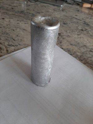
At the cost of severe embarrassment, I am going to post a picture to give an idea of where I am going, with hopes of input. My choices now are learn CAD or keep making chips so I am choosing chips....
The more I get into this, and with the number of plans available on line, anyone wanting one, especially with this group of talented individuals is going to do what I am doing, using what is in stock and winging it, buy plans and order what is needed. But when I started this, I hoped to end up with a set of plans (or group of ideas) that drew on input from a few and that we can post as original (or semi original)
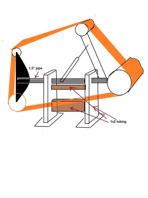
So, I have been trying to do something slightly different but yet, you still need a drive wheel, platen and tension wheel. Hard to vary too much from that. The thing I have been hung up on is building the motor mount and platen around a round piece of stock (pipe or bar) instead of building a hinge assembly to allow the platen to go vertical or horizontal. I think horizontal has more appeal with those that work with wood (sanding end grain.....hate sanding end grain...) and vertical more for metal workers, especially knife makers as proven that these sanders are mostly promoted by knife makers.....Chad.....

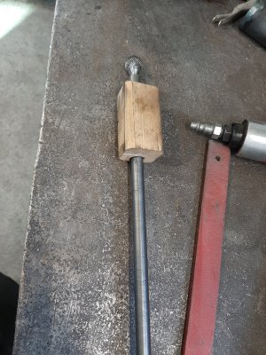
. Looking at my stockpile. I have lots of 1.5 " pipe, and other sizes. But I also have a couple lengths of 1x2 tubing from a project that did not materialize. So today, I kind of settled on a directtion to go in, but not sure of the specifics. This is where you come in. Don't be afraid to say it is not good but at the same time, have an open mind.
Remember, I have not even seen one of these things so experience is squat!
So here goes the embarrasement .....unless you are one of those guys that goes right to the photo first!

Some explanation......
The motor drive wheel is on the left side, looking at the platen. Picture is kind of goofy there. The video above mentions this due to the left hand threads on the motor.
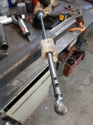
Motor mount and platen rotate as one with the round pipe being the "axle".
Bushings and collars will be used where necessary but the axle must be removable so not welded at both ends. I picture the motor mount assembly being welded in place.
The axle passes through the 1x2 tubing, bushed for stability.
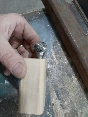
The platen has 2 different sized wheels so if you need a narrower wheel, rotate (tilt) it back and for a wider wheel, rotate it the other way. Vertically, it has a flat surface. This establishes a 3 in 1 attachment instead of needing more attachments. Downside I can envision is having the tensioning mechanism flexible enough to accomodate a single wheel contact set up with the platen set up. Know what I mean?
Will the 1.5" pipe be rigid enough for an axle? I am thinking a solid insert from the front to the first bulk head might be necessary.
I think that is all I got for you right now. I probably missed some points that are spinning around in my head but hoping this gets the conversation going.
Let me know what you think.
Cheers,