2x72 sander

Do you have a 2x72 sander?

  • Yes

    Votes: 10 23.8%
  • No

    Votes: 14 33.3%
  • Want one

    Votes: 18 42.9%

  • Total voters
    42

ShawnR

Ultra Member
Premium Member
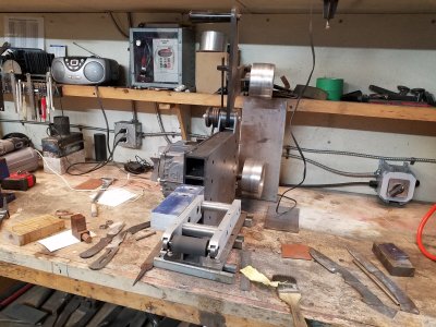
Well, this is the largest project I have taken on with my lathe. Did I mention I might want a larger lathe...? :rolleyes:

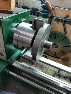
Worked through the steps I outlined above. My lathe is a 10" but these 6 inch pieces, with my chuck, max out the jaws. Apparently, my measuring tools too as I only go up to 6" vernier calipers so making a press fit might be more "guessetimate" than measurement.... I don't think you have a lot of trial and error room in press fitting.

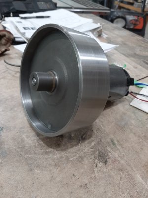
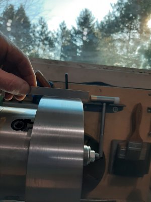
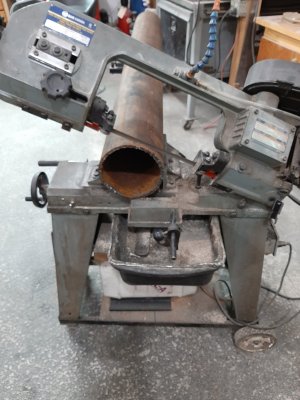
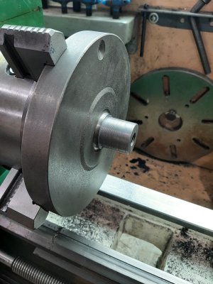
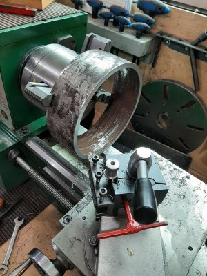
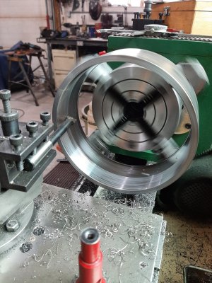
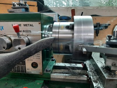
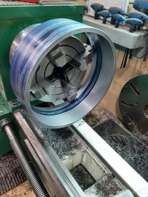
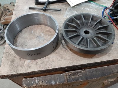
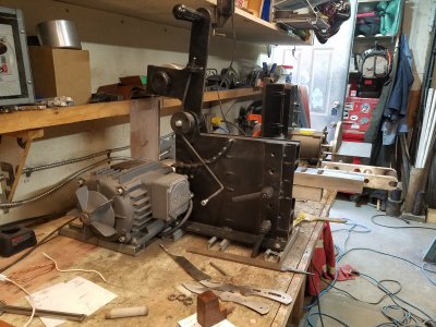
Turning the grooves off the hub was easy. The hub is cast iron but machines nice. Cleaner than some cast I have worked with. I just cleaned up the rim as I don't know how far I will need to go till I get the pipe cleaned up. That in itself is taxing me. Probably mostly lack of experience on my part, but there are also machine limitations in the equation. @RobinHood gave me some concerns to watch for and I tried to be wary of it but not sure my little chuck would be bending the pipe with .258 walls. All the same, I figured good to be careful. Before I started, I used a grinder to clean the majority of the rust off of the inside and outside of the pipe, but in doing this, I then found it hard to get a perfect alignment in the chuck because of the variations in the surface caused by the grinder. I think if I were to start over, I would do it slightly differently. Near the end, (ie when I had it almost one clean inner surface, I noticed chatter so I switched to a heavier boring bar with a HSS bit in it and it cut nicer than the carbide boring tool I used for most of the cutting. I should have done it all with the heavier bar but it has a longer overhang at the end so can't get all the way in. And I was thinking that the rusty inside would beat up the HSS more than the carbide All good experience. though Still working on it. Found out that my cross slide does not fit under the pipe in the lathe so need a long tool to cut the outer surface. I think I will be using the boring bar on the outer surface just for reach.

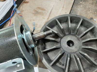
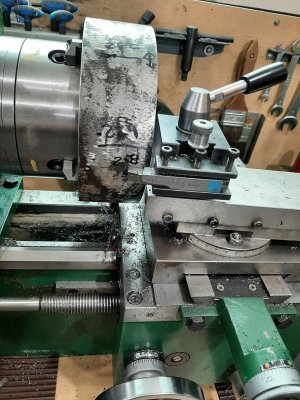
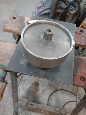
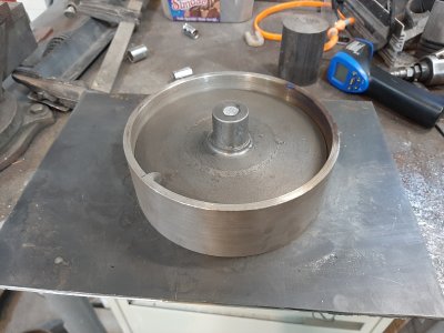
From the pic of the back of the hub, you can see what I have to work with for material thickness on the edge, which will be press into the pipe to form the drive hub I think there is lots of material there if I can match a maximum pipe thickness with minimal removed from the hub. Will know more when I get the pipe to good inside and outside surfaces. The hub is good to go now, I think, so anything from here on it is just to get the fit I need.
 

Attachments

  • Cutting stock.jpg
    Cutting stock.jpg
    390.1 KB · Views: 15
  • Flywheel with v grooves.jpg
    Flywheel with v grooves.jpg
    417.1 KB · Views: 16
  • Smooth hub.jpg
    Smooth hub.jpg
    397 KB · Views: 15
  • Truing edge.jpg
    Truing edge.jpg
    468 KB · Views: 16
  • Truing belt surface edge.jpg
    Truing belt surface edge.jpg
    497.4 KB · Views: 16
  • Mating surfaces.jpg
    Mating surfaces.jpg
    513.5 KB · Views: 16
  • Boring.jpg
    Boring.jpg
    510.1 KB · Views: 16
Last edited:

ShawnR

Ultra Member
Premium Member
Also, I would like to mention that you will need to crown both your drive wheel and tracking wheel or you may have a hard time keeping your belts on. You are welcome to take a look at my 2x72 if you like; it has some great features and some mistakes to be learned from.

Good luck with your project.

Cheers,

Chad

Chad, I read somewhere that you should only crown one pulley, the guide one. So you found that you needed two crowned? Good to know.
 

Crosche

Super User
Chad, I read somewhere that you should only crown one pulley, the guide one. So you found that you needed two crowned? Good to know.

Yes, both my drive and tracking pulleys are crowned; I tried running a machine with only a crowned tracking pulley and couldn't keep the belt on it. My drive pulley measures 4.70" outside diameter and 4.96" middle diameter and it is 2.25" wide with a 5/8" bore. If I calculated correctly, the crown taper is just over 6.5 degrees.
Also, be very aware of the distanced between your drive pulley, tracking pulley and the wheels on your tooling arms which will vary due to the size and type of wheel or platen. I am worried that with such a large drive pulley you are going to use a lot of belt length and really limit the size of contact wheels your grinder will accommodate. My machine only has a 5" drive wheel and I find getting some contact wheels to fit is a challenge.

If you are not heavily invested in making a drive pulley, my friend has a 4" drive wheel from his 2x72 which he said he would sell for $25.
 
Last edited:

ShawnR

Ultra Member
Premium Member
Yes, both my drive and tracking pulleys are crowned; I tried running a machine with only a crowned tracking pulley and couldn't keep the belt on it. My drive pulley measures 4.70" outside diameter and 4.96" middle diameter and it is 2.25" wide with a 5/8" bore. If I calculated correctly, the crown taper is just over 6.5 degrees.
Also, be very aware of the distanced between your drive pulley, tracking pulley and the wheels on your tooling arms which will vary due to the size and type of wheel or platen. I am worried that with such a large drive pulley you are going to use a lot of belt length and really limit the size of contact wheels your grinder will accommodate. My machine only has a 5" drive wheel and I find getting some contact wheels to fit is a challenge.

If you are not heavily invested in making a drive pulley, my friend has a 4" drive wheel from his 2x72 which he said he would sell for $25.

Good to know about the crowning of two.

When you say contact wheels, do you mean when the sander is configured for working with one pulley, versus a flat platen? Or the wheels in the general construction? I have been thinking I should take a rope and lay out some stuff to get an idea of dimensions. I like compact but not non functional. You make a good point. I don't have a belt yet for sizing. Could get one today probably in town, I think.... Couple of places I checked have none though. I will hold off on buying the pulley from your friend, Thanks for the offer. Most of this stuff I do is to learn how to do it, as much as that is a battle sometimes,...... :rolleyes:

I finished a melting furnace recently and it is pretty much ready to start melting aluminum so I could cast one that size easy enough. A larger one, like this size, was going to be the limit of my crucible and.....I have not melted anything yet..... so that will be another learning curve I have been avoiding while I am figuring this other stuff out. I plan on casting the other pulleys. They will just start out looking like a soup can, I think. They look easy enough. I was trying to keep the motor speed down, ie larger drive pulley, but have not tested the motor to see what it can do for RPM. Any idea what your motor spins at? What type of motor did you use? I figured my chassis design will hinge around the drive pulley and platten so will see how this drive pulley turns out. How long is your platten?

Can you post a couple photos of your sander please?

Thanks
Cheers,
 

Attachments

  • PLaten image.jpg
    PLaten image.jpg
    421.5 KB · Views: 13
  • Singlewheelcontact.jpg
    Singlewheelcontact.jpg
    119 KB · Views: 14
Last edited:

Crosche

Super User
Good to know about the crowning of two.

When you say contact wheels, do you mean when the sander is configured for working with one pulley, versus a flat platen? Or the wheels in the general construction? I have been thinking I should take a rope and lay out some stuff to get an idea of dimensions. I like compact but not non functional. You make a good point. I don't have a belt yet for sizing. Could get one today probably in town, I think.... Couple of places I checked have none though. I will hold off on buying the pulley from your friend, Thanks for the offer. Most of this stuff I do is to learn how to do it, as much as that is a battle sometimes,...... :rolleyes:

I finished a melting furnace recently and it is pretty much ready to start melting aluminum so I could cast one that size easy enough. A larger one, like this size, was going to be the limit of my crucible and.....I have not melted anything yet..... so that will be another learning curve I have been avoiding while I am figuring this other stuff out. I plan on casting the other pulleys. They will just start out looking like a soup can, I think. They look easy enough. I was trying to keep the motor speed down, ie larger drive pulley, but have not tested the motor to see what it can do for RPM. Any idea what your motor spins at? What type of motor did you use? I figured my chassis design will hinge around the drive pulley and platten so will see how this drive pulley turns out. How long is your platten?

Can you post a couple photos of your sander please?

Thanks
Cheers,

I will post photos of my machine tonight. You are welcome to have one of my worn out belts for sizing purposes.
By contact wheels, I am referring to the surfaces or wheels that you grind with, the ones that come into contact with your work. The great thing about a 2x72 is that the front wheels can be changed out very quickly to accommodate different diameters of contact wheels and different sizes and shapes of platens. Many 2x72 grinders can accommodate 12" diameter contact wheels all the way down to 1" contact wheels and 7"~9" platens.
 

ShawnR

Ultra Member
Premium Member
Thanks for the belt offer but if not available locally, I will order. I have been building an order with KBC and will finally place it when I need something in particular like the belt. Thanks for clarifying the "contact ". I figured that but did not want to assume. As of right now, I am only planning a flat platen but will keep wheel size in mind when I start working on the chassis. Having a good day so far cleaning up the rim. I am optimistic we will be successful......;)
 

Tom O

Ultra Member
I use a 6x6x9” square tubing for a crucible for casting aluminum and a clay graphite for brass. I have bolts in the two corners for lifting lugs. The pic below shows my unconventional tongs ( the lifting tabs were not welded yet ) the lower plate of the crucible has a eye on the corner for pouring. The lifting tabs are placed over the bolts and by gripping the handle/lever keeps pressure on the crucible so there is no slippage and since you are picking it up from the corners you have a built in pouring spout I use a coat hanger through the baseplate eye to pour. With this design you could even lift by the lower handle while keeping the grip on the crucible.

AD425418-F3B3-4A82-A0E6-506A89386482.jpeg 6C14C039-C367-4F94-B207-7CB3444E0DE6.jpeg
 

ShawnR

Ultra Member
Premium Member
Thanks Tom. I built a similar crucible for lead several years ago but made the mistake of putting the lifting eyes on the sides, which of course, made pouring difficult. It will be easy enough to fix when I get to that stage. Obsessed with getting this drive wheel assembled right now. Having said that, do you have any photos of the sieve you use to clean out the molten aluminum? I will need to get/make that before melting anything.
 

ShawnR

Ultra Member
Premium Member
Would it make sense to start a collaborative fusion file for a site designed grinder?

That would be great! I wanted to suggest that when I started this thread but I cannot contribute to it so I didn't. I am still trying to figure out how to draw a piece of square tubing in a CAD it. (and I moved to FreeCAD ). And then to draw two pieces and somehow connect them......nope.... so I will just be the test dummy. Thanks Alex!
 

ShawnR

Ultra Member
Premium Member
I am thinking this is not the most efficient way to come up with a drive pulley....:rolleyes: Might have to fire up that furnace sooner than I thought, but learning lots about setting up. Spent most of the day cleaning up the pipe flange while trying to ensure that the flange is concentric. Got there ...close enough, I think but now need to fit it to the flywheel. I may need to borrow a 12" caliper from a friend or take it to another friend to finish it. I don't want to just throw the flywheel in the lathe and start turning it down cause I think I might botch it. Would be nice to have some numbers to shoot for. Here are some photos of todays activities.

Because of the cross slide hitting the flange, needed to use the boring bar for reach
Found that a shop vac works great to clear the smoke ...personal localized exhaust system
I spent way too much time swapping flange back and forth trying to maintain/fix concentricity. Has to be an easier way....?
But got it close. Need to remove about 0.160 " total from flywheel diameter to press flange on. Thinking this is better than thinning the flange, which sits about 0.230"
Last pic is that of a piece of stock I have. I believe it was purchased as plastic bearing material. I am thinking it might work as the other wheels. Is anyone familiar with it? I got it from a hydraulic shop many years ago when I built the backhoe. I think, if I recall correctly, it was supposed to be good stuff. I could turn an axle and be done? Input? I guess if it does not work, I could then make the wheels from aluminum. Just a thought. I found this link. I wonder if the GGG is supposed to be a GGB https://www.ggbearings.com/en/our-products/engineered-plastics-bearings
 

Attachments

  • Tool bit too short.jpg
    Tool bit too short.jpg
    530 KB · Views: 14
  • Smoke control.jpg
    Smoke control.jpg
    470.1 KB · Views: 13
  • Boring inner.jpg
    Boring inner.jpg
    573.3 KB · Views: 11
  • parts to mate.jpg
    parts to mate.jpg
    539.2 KB · Views: 11
  • Plastic bearing stock.jpg
    Plastic bearing stock.jpg
    280.9 KB · Views: 11

ShawnR

Ultra Member
Premium Member
I was surfing around today, looking for more ideas, etc. I found a video of someone
who made a sander from a treadmill motor....so much for being original on my part :rolleyes:

I should have known that if you have an idea, chances are that it has been done, and is on youtube somewhere. So plunging forward, this is my disclaimer. I wanted this to be a group project, and still can be but will probably be a collection of ideas from the internet. There are countless ways to get it done. I had originally suggested using round stock for the main structure, my reasoning being a nice solid pivot point but looking at my stock, might be, begrudgingly, reverting to square stock....only because it has been done so much, I wanted to be different! Oh well. If it works, ....

@molyknow if you are interested in doing CAD drawings, let me know what you need as I step through the prototype. I can supply numbers as I go, if you or anyone with CAD skills would like. It would be nice to end up with nice drawings added to the Plans section. Not sure me being the lead designer/prototyper is our teams best choice....but I will take the hit for the team..o_O

Some notes.. I like this design linked below, basically, so might build on it.... And he is not selling plans or anything so I don't feel bad about using it to get started.

I noticed in the video below, he does not change the width of the drive pulley, but rather just loops the belt around it as is. The pulley is about 1 " wide. I forget exactly. What is your take on this? Worth widening the drive pulley to the full belt width? I would think that a narrower pulley will accelerate wear on the belt as it flexes and stretches around it so I think I still like the idea of a full width drive pulley. But, what do you think? As I read through this again, looking for errors, I thought that the natural narrowing of the drive pulley almost imparts a crown in the drive belt....mmmmm...

His platen does not rotate and that was a mandatory option for me, so I will incorporate that somehow, round pipe or hinges.

His motor mount, cut from his treadmill, is more solid than the ones I am finding but his is what I pictured. So, mine will end up being similar, just shop made.

He uses an aftermarket speed controller. I got mine out of the treadmills I scrapped. That will be the last thing I work on. If anyone has any questions about this aspect, post your questions. I am sure others here have more experience than me.

So, back to the saga of the drive pulley flange.

Cheers,


ShawnR

Ultra Member
Premium Member
And here is a link to the electronics end of things. He stated the motor can go up to 7900 RPM so I guess my concerns about RPM were for not. A smaller drive pulley will be fine.

 
Last edited:

Crosche

Super User
Pics of my grinder w/ small wheel attachment.
 

Attachments

  • 20210312_171419.jpg
    20210312_171419.jpg
    610.5 KB · Views: 16
  • 20210312_171425.jpg
    20210312_171425.jpg
    628.7 KB · Views: 16
  • 20210312_171440.jpg
    20210312_171440.jpg
    569.2 KB · Views: 15

ShawnR

Ultra Member
Premium Member
Thanks Chad. That is a solid looking sander! I may be under designing mine. Seeing your single wheel gives me an idea. I have been only picturing a flat platen this far, but perhaps could incorporate the option that the flat platen turned on end becomes a single wheel. I think in the Jeremy design, linked above, he suggests other fixtures, ie, a single wheel. Gives me more to think about.

A friend dropped by with 8" Verniers yesterday and so I could continue my fitting of the flange to the hub. He also mentioned/reminded me that the pipe will expand quite a bit with heat. I was planning on mating them with temperature differential anyways but that gave me more room to play with. I turned the hub to only within about .010 as a start. I then used a propane torch on the flange (to about 80C?) and a snowbank for the hub. I slid it on part way, and it stopped. So I went to Acetylene. checking temp with a heat gun as I went, trying to keep it even. I was able to get the hub out, do it again, but heated the flange to about 180C this time, with the hub back in the snow bank. I used 3/4" tool bars in the flange to set the height and upon assembly, the hub dropped in! I will check the balance today and do a final truing up, I hope and then move on to the chassis.

For anyone reading this as a "how to", this flange episode might be a "how not to" but what the heck, having fun. Running the sander at the end will be the final test as to whether this is a reasonable alternative to getting a solid aluminum drive wheel. With this 6.25 inch OD wheel, my motor will be running about 3000 RPM for a 5000 SFPM belt speed, which I have read is the desirable surface speed for knife makers. @Crosche correct? That puts the motor about mid range, if the info that 7900 rpm is the max for these motors, so I feel good about that.

Also, a 3200 (3250?) RPM motor is fairly common, so this size drive wheel opens up options if variable speed was not a requirement in your design.

Cheers,
 

Attachments

  • Part way oh oh.jpg
    Part way oh oh.jpg
    350.6 KB · Views: 7
  • Thermo fit.jpg
    Thermo fit.jpg
    390.8 KB · Views: 7

Crosche

Super User
@ShawnR you are correct about the surface speed; however I don't think drive wheel temperature will be an issue. Even after a long grinding session you can still touch the drive wheel on my grinder with bare hands and considering that your drive wheel is much bigger and has more mass this should be even less of a problem for you. The greater concern, I think, will be dynamically balancing the drive wheel so it doesn't shake everything off of your bench. :)

Also, please note the location of my drive wheel; it is too far away from the chassis and thus makes it difficult for me to change belts and contact wheels. Realistically the driver wheel should be at least 2"~3" closer to the chassis to extend the range of travel of the tooling arms and give me more belt to work with. This is a major challenge when we design a machine for the group because of the different motor configurations and drive wheels that people may use. Our design will have to make provision for mounting all types of motors.

Cheers,

Chad
 

RobinHood

Ultra Member
Premium Member
Looks like you are making good progress. Nice looking drive wheel. Good “rescue” of the stuck steel tire off the hub. Yes, pipe does expand a lot.

Please don’t take this the wrong way, as nothing happened this time, but be very careful and aware of how far the jaws are sticking out while machining.

There was not much thread engagement in your set-up. Rule of thumb is jaws don’t go past the edge of the chuck by more than 1/3 the length of the jaw, to ensure 2/3 to no less than 1/2 length engagement. Look at your pictures: I would be surprised if you had more than two threads hanging on.

D2889A1B-C63B-43C9-B0A6-93876114CCE6.jpeg

B8A3C783-5CA8-4DB8-823D-1EA5D5EDA295.jpeg

The threads on the pinion do not start right at the end, neither do they on the chuck jaw. You may want to mark a “no go zone” beyond which you should not extend jaws.

Here is what TMX recommends for safe practice (I just picked a manufacturer, not affiliated. You can search for others, info is more or less the same for all of them).

7ABBADBB-6D31-4280-B753-54A55A67AF42.jpeg

I’ve had a 4” PVC pipe come out of a 4J at 1000 rpm. I was doing ID work and luckily the piece caught on the boring bar. In my case it was not because the jaws were too far out, but because the pipe deformed under the jaw pressure and walked out - hence my original caution to you. I do agree that you probably did not deform the steel pipe sufficiently to be an issue. But I bet that if you used an inside micrometer, you would still have seen the 4 “jaw lobes” on the ID (and then later on the OD, when you cleaned up the outside).
 

ShawnR

Ultra Member
Premium Member
Looks like you are making good progress. Nice looking drive wheel. Good “rescue” of the stuck steel tire off the hub. Yes, pipe does expand a lot.

Please don’t take this the wrong way, as nothing happened this time, but be very careful and aware of how far the jaws are sticking out while machining.
@RobinHood ...I would be an idiot to take good safety advice the wrong way! That is why I hang out with you guys...I don't know way more than I know....

Thank you for the specifics.....interesting. I did not know about the 1/3 rule but I did know that it did not look good at all......but, yes, I did it anyways.....:eek: 
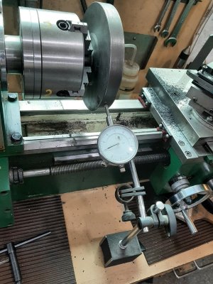
I only ran at the slowest speed the lathe would go 150? I think, and took very light cuts. Thank you.


@ShawnR you are correct about the surface speed; however I don't think drive wheel temperature will be an issue.
Chad

I was not too worried about drive wheel temperature. Misinterpretation? But maybe just never thought of that . Thanks for the input on the drive wheel positioning. I am starting to look at chassis options.

I finished the drive wheel today. As you suggested, I crowned it a bit. about 1.5 degrees per side. I think it looks good but running a belt over it will be the deciding factor. I made a mandrel for it so if I have to rechuck it, I should be able to to increase the crown. I also ran the assembly on the bench. It seems really smooth but have not even done a static balance on it. I just want to see how it looked. Hard to tell but the motor is running. I should have put a line on it.


Attachments

  • Assembly.jpg
    Assembly.jpg
    414 KB · Views: 5
  • Crown.jpg
    Crown.jpg
    275.7 KB · Views: 5
Last edited:
Top