• Spring 2024 meetup in Calgary - date Saturday, April 20/2024. discussion Please RSVP Here to confirm and get your invitation and the location details. RSVP NOW so organizers can plan to get sufficient food etc. It's Tomorrow Saturday! you can still RSVP until I stop checking my phone tomorrow More info and agenda
  • We are having email/registration problems again. Diagnosis is underway. New users sorry if you are having trouble getting registered. We are exploring different options to get registered. Contact the forum via another member or on facebook if you're stuck. Update -> we think it is fixed. Let us know if not.
  • Spring meet up in Ontario, April 6/2024. NEW LOCATION See Post #31 Discussion AND THE NEW LOCATION

2x72 sander

Do you have a 2x72 sander?

  • Yes

    Votes: 10 23.8%
  • No

    Votes: 14 33.3%
  • Want one

    Votes: 18 42.9%

  • Total voters
    42

ShawnR

Ultra Member
Premium Member
Coming up the list is to build a 2x72 sander. I attached a poll here just for fun and curiosity as it seems like this is a popular project for home hobbyists. A friend approached me a couple of months back with some questions and, since then, I have spent too much time spinning my wheels on it, so it is time to move forward. on building one. I was hoping we could design one together and then post the plans in the "Plans" section. As those that have been on committees before, the more people involved,the longer a project takes but at least we will all have some input. There are tons of videos and plans available on line. For me, here are my thoughts and options. You might be in a slightly different, or very similar situation.
I don't have square tubing that slides nicely into other square tubing, which seems to be a common thread with plans on line.
I do have lots of round tubing/pipe/DOM tubing and I have a metal lathe that works better with round stuff than square stuff
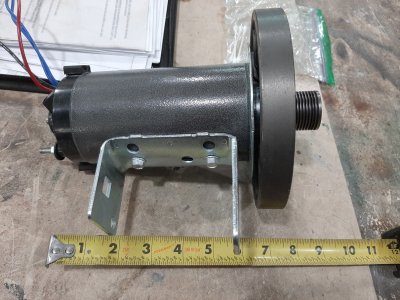
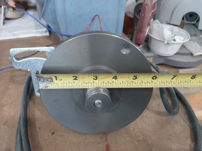
I have scrapped a couple of treadmills and have the motors and controls boards (read variable speed, 2-3 hp )
These sanders have been mentioned several times for sharpening tool bits...right up our alley
I think the round pipe lends itself to a tilting sander better/more easily done than with square tubing (but that mechanism does not look too difficult either)
So, rather than post pics after it is done, I thought I would see what the group has to say. And wondering if there is interest in making this a group project. I lack CAD skills but am trying so won't even post what I have so far. but eventually, plans will need to be drawn to post in that forum. Mine will be awful, functional, but awful....just saying!

For now, start with the poll. I would be interested in seeing who has built one and if they used plans, which plans. or just winged it. I would guess "winged it", from this group, is going to be the answer.
 
Last edited:

Brent H

Ultra Member
@ShawnR - I have plans for one built up out of 1/2” plate sheet - will post as soon as I can. It is one off of a knife makers ideas and a basic smash up of several other “machines”, Plans and ideas. It is laid out as a bolt together but I would slot weld it or full weld - will be heavy.
 

ShawnR

Ultra Member
Premium Member
@Brent H ...I have seen some bolt ups. My friend showed me the plans he has but not sure if he bought them so I won't mention where they are from or repost them. They look good and well done, but I think a rather large amount of work for something we can do more easily with round stock, of some sort. Again, looking at my stock and looking for a sander in it. The more I look,the easier they look to build. Some plans are really simple and I think that is the way to go, then I see other Gucci plans and think, that is pretty sweet so it comes down to what the builder wants and has access to. Maybe not a good project for a group like this cause there is such a diversity in stock items, (if that was a building criteria) but I thought if some have built one, maybe they would add their likes and dislikes about the project.

So far, I think the tilting feature of the sanding belt is really appealing, as is the ability to tilt the table sharply down. This is a knife makers need for the sharpening/shaping profile, I guess. Also, I could see a benefit to swapping out a flat grinding surface for a wheel so you can do inside radiuses. (radii?)

Lots of good ideas out there. The more I look, the more I want one. My focus will be on using a treadmill motor and control board for the drive so hopefully, that helps others with the drive system. Some guys are buying 3 phase motors and putting VFD's on them. Cool, but to me, it is just a belt sander. I would put that motor on my lathe instead, given the option. or drill press.....just saying..;)

But in the end, we can post a plan, in our forum, that we did not take from the internet and is a collaboration of member's inputs. Cool, I think.
 

ShawnR

Ultra Member
Premium Member
So, to get the discussion going, here is what I am starting with. ....the pulley (more like a flywheel) on the motor is about 5 3/4" in diameter and about 1" wide. The grooves you see are for a micro v belt. So, to me, the wheel is too narrow to be a direct drive pulley, and I would like a larger diameter to increase surface feet per minute. Most knife makers ( correlating to efficency) seems to be about 5000 sfpm. I would like to keep the RPM in a reasonable range, although not sure what that is yet for these motors. Having said that, I have not tested the motor to see what it actually like to run at. But I had a 7 inch diameter in mind ..about 2700 RPM. I would start with anything from the existing diameter to a custom made 7 incher (when stock avails itself to me. )
The thread holding the flywheel on is a 1/2" left hand so easy enough to make a whole new drive pulley. Casting one? Making one out of pipe and plate? Modifying the flywheel? I have seen plans for shop built stuff before using MDF as the pulley. On a machinist's forum, this would be frowned upon but practically speaking, to bond a piece or two of MDF to the existing fly wheel to have a 2" wide drive pulley,with the cast iron flywheel as the base ...... might actually work....o_O

Mounting the motor...I don't like the existing mounting brackey but would reuse the holes in the motor chassis.

I would put a tach on it but one that displays SFPM instead of RPM. Couple ways to do this, Microcontroller (Arduino) to do the math and display it or a pulley sized so that the RPM reflects the SFPM ie if the circumference of the sensing pulley is ten inches, then SFPM is 10 times the tach display or add magnets as multipliers.

I have 4 scrapped treadmills and 3 complete controllers/motors. One motor where the controller was pooched. So saying, if you want to do this and have not looked into Treadmills as resources, it might interest you.

Cheers,
Shawn
 

Attachments

  • Treadmill motor.jpg
    Treadmill motor.jpg
    501.1 KB · Views: 13
  • TM motor flywheel.jpg
    TM motor flywheel.jpg
    336.2 KB · Views: 13
Last edited:

Tom O

Ultra Member
You could always weld/braze 3/8x1/8 strips on the inside sliding tube and machine for fit that way the seam isn’t a problem.
 

6.5 Fan

Ultra Member
Premium Member
I will be watching this thread closely, always wanted one but to many other projects.
 

ShawnR

Ultra Member
Premium Member
You could always weld/braze 3/8x1/8 strips on the inside sliding tube and machine for fit that way the seam isn’t a problem.

Yes, I have done that in the past. Or groove the inner piece to slide around the seam. There is also a guy online that suggests a block of wood or aluminum to guide a grinder or cutter through the inside to remove the seam. All great options. I was just looking at my stock and thinking do something different and with what I have, and an excuse to use the lathe, somewhere in there. It is more of a "lets do something different" rather than just get it done project. (This time.....;) )

Thanks
Cheers,
 

Tom O

Ultra Member
I’ve seen that before as well as the tool bit being pulled through by threaded rod this will have to go on the to do list I think I have some square stock that size.
 

John Conroy

member
Premium Member
It would be fairly easy to duplicate that "Seams Impossible Tool" or you could go the Jeremy Schmidt route and make tubing from flat bar.

<iframe width="560" height="315" src="
" frameborder="0" allow="accelerometer; autoplay; clipboard-write; encrypted-media; gyroscope; picture-in-picture" allowfullscreen></iframe>
 

ShawnR

Ultra Member
Premium Member
It would be fairly easy to duplicate that "Seams Impossible Tool" or you could go the Jeremy Schmidt route and make tubing from flat bar.
I think that was the first video I watched on these things. He did do a nice job but I think a harder way to go than finding materials that work together without the welding.

@Dabbler , that is not the same guy I saw but same idea. Looks like he has put together a nice tool. Thanks
 

ShawnR

Ultra Member
Premium Member
A friend dropped off some 6" pipe yesterday. My thought is to make it fit over the existing flywheel from the treadmill. Cutting a 2" (2.25") wide band, then making it a press fit onto the flywheel would be an easy conversion I think....not sure if I have the skill set to make a concentric, press fit, secure modified wheel, but I have about 6 feet of pipe to learn with.

Please insert suggestions but here is my plan

Load flywheel in lathe, making it turn as true as possible (I don't have a 1/2" left hand mandrel for centre thread) and turn small micro belt hub down to a smooth surface (to be used a mandrel later)
Turn it around and mill outer edge, just cleaning it up
Remove and install 6 pipe into lathe and clean up inside, turn to press fit dimension for flywheel. When there, remove and install pipe onto flywheel
Reinstall assembly into lathe, held by centre mandrel and true up outer edge for belt surface.

Does that sound about right? Not sure if there is a better way to do it, ie, turn pipe first, then fly wheel? Maybe turning outside of fly wheel is easier than boring inside of pipe so mill pipe first?

What do you think?
 

RobinHood

Ultra Member
Premium Member
I think your procedure should work.

One thing: it is easy to distort the pipe. If you cut off say a 2.25” wide ring and clamp it in either the 3J or the 4J for ID turning, you will most likely end up with either a 3 or 4 lobed “ellipse“ of an ID when you release it from the chuck. Then it won’t press fit properly onto the flywheel.

Depending on the wall thickness of your pipe, it might be a good idea to weld in temporary cross supports and use the 4J on the supported spots. Cut your ring about 4-6” wide so that you can machine the bore of the first 2.25”. Once you have the ID to where you want it, part off the 2+” ring you need (the “+” part being for machining allowance once the ring is pressed on the flywheel to true up the sides).

It is tempting to just cut a ring of 4-6” wide and grab it in the chuck - thinking that one can just machine the “free” first 2” or so. Bad things can/will happen fast (the speed at which these bad things happen depends on the distortion of the pipe wall): the ring will walk right out of the chuck jaws. The harder you chuck it up, the faster it comes out.

Joe Pie has a two part video showing the distortion I am talking about (and how to fix it)


ShawnR

Ultra Member
Premium Member
Thanks Robin. I just finished the flywheel when I saw this. Your timing is perfect. Good points. I will check out Joe's vids and reassess and report back. At least with 6 feet of pipe, I have a few cracks at it...:D
 

Crosche

Super User
Here is a YouTube video from Fireball Tooling on how he removes welding seams:


Also, I would like to mention that you will need to crown both your drive wheel and tracking wheel or you may have a hard time keeping your belts on. You are welcome to take a look at my 2x72 if you like; it has some great features and some mistakes to be learned from.

Good luck with your project.

Cheers,

Chad
 

PeterT

Ultra Member
Premium Member
Maybe another way around the tubing sleeve issue vs dealing with weld seam & rounded corners & potentially sloppy sliding fit is - Just make your internal bar however it turns out, like maybe you want to flycut it smooth so its going to be an oddball dimension anyway. Then make the socket from 4 slabs of metal with whatever clearance you prefer. Could be bolted or welded or whatever. Depending on the design I don't think there is a requirement that the bar as to be square section or the external socket edges even flush. I think its more about the nice sliding fit & lock mechanism.

1615403796753.png 1615403814046.png
 

Tom O

Ultra Member
I would think it would be between 1/16 and 1/8” crown, at work we just built up the roller with masking tape till it centered on the conveyors.
You could put it together and build up the surface to see what you need for a crown and machine them last.
 
Top