• Scam Alert. Members are reminded to NOT send money to buy anything. Don't buy things remote and have it shipped - go get it yourself, pay in person, and take your equipment with you. Scammers have burned people on this forum. Urgency, secrecy, excuses, selling for friend, newish members, FUD, are RED FLAGS. A video conference call is not adequate assurance. Face to face interactions are required. Please report suspicions to the forum admins. Stay Safe - anyone can get scammed.

What's this 9.5" long Test bar telling me?

Susquatch

Ultra Member
Administrator
Moderator
Premium Member
I doubt I was hallucinating because I was staring at my original felt pen scribble of 0.0012" & that figure backs up my notes. Maybe they are like cheese & must be used before a Best Before Date lest they revert to a shiny banana.

Poorly heat treated 4140 relaxing over time?
 
Probably good advice for most people Degen. But we are all different in one way or another. A few guys (like me) just gotta poke the beehive......

Curiosity will prolly kill me some day - if old age doesn't get me first.
I have to admit, I have to poke it too, just because.....
 

Dabbler

ersatz engineer
Poorly heat treated 4140 relaxing over time?
If you don't mind a little story:

Bert has built a bunch of metrology equipment over his 70 years as a tool and die maker (most of which I now own). They included 4140, D2, A2 (forged by Castro's brother in law) and other random tool steels. It was always standard practice 'way back then' to rough mill the piece, heat treat it, and the let it rest for 6+months. Even D2 tool steel can 'relax' over time. He then rough ground it and left it for another rest period, and then finish ground it. All of the tools he made were within 2 tenths - square and in dimension.

Of course nobody that is in the production end of things wants to do these strict procedures, so I'm sure that these bars can easily move over time right after manufacture. The good news is that you can put YOUR test bar in YOUR lathe, mark its position and tool post grind it to perfection. then it can become a permanent part of that lathe for refining and re-calibrating your setup.

The Suburban bars were done Bert's way under the Taft - Pierce brand name, and were perfect.
 

Susquatch

Ultra Member
Administrator
Moderator
Premium Member
If you don't mind a little story:

Bert has built a bunch of metrology equipment over his 70 years as a tool and die maker (most of which I now own). They included 4140, D2, A2 (forged by Castro's brother in law) and other random tool steels. It was always standard practice 'way back then' to rough mill the piece, heat treat it, and the let it rest for 6+months. Even D2 tool steel can 'relax' over time. He then rough ground it and left it for another rest period, and then finish ground it. All of the tools he made were within 2 tenths - square and in dimension.

Of course nobody that is in the production end of things wants to do these strict procedures, so I'm sure that these bars can easily move over time right after manufacture. The good news is that you can put YOUR test bar in YOUR lathe, mark its position and tool post grind it to perfection. then it can become a permanent part of that lathe for refining and re-calibrating your setup.

The Suburban bars were done Bert's way under the Taft - Pierce brand name, and were perfect.

Love it! Great story!

Material science is not my thing but I confess I am not really surprised.
 
If you don't mind a little story:

Bert has built a bunch of metrology equipment over his 70 years as a tool and die maker (most of which I now own). They included 4140, D2, A2 (forged by Castro's brother in law) and other random tool steels. It was always standard practice 'way back then' to rough mill the piece, heat treat it, and the let it rest for 6+months. Even D2 tool steel can 'relax' over time. He then rough ground it and left it for another rest period, and then finish ground it. All of the tools he made were within 2 tenths - square and in dimension.

Of course nobody that is in the production end of things wants to do these strict procedures, so I'm sure that these bars can easily move over time right after manufacture. The good news is that you can put YOUR test bar in YOUR lathe, mark its position and tool post grind it to perfection. then it can become a permanent part of that lathe for refining and re-calibrating your setup.

The Suburban bars were done Bert's way under the Taft - Pierce brand name, and were perfect.
I am not surprised at hearing this, as machining or grinding occures it changes the stress levels in the material which redistributes the internal forces which causes movement. The "gradual" change in forces is relaxing.
 

PeterT

Ultra Member
Premium Member
I confess that I was predisposed to favor the 2 collar bar because it can be cut to align with the spindle axis and although its not the same as the adapter issue you referred to above, anything that Plugs into something else without an adjustment introduces the chance of error. By cutting the two collar bar in the spindle of question, it becomes an extension of the spindle without any adapters.

However, enough members have suggested the spindle bar is a reliable tool so I felt it appropriate to test it myself. Seems like you have done that for me so I may have wasted my money - curiosity killed more that a cat. But of course, you are also right, at least I will have a nice bar of 4140 when it gets here.

What bothers me most about this is the thought of how many people have bought those bars and then jacked their lathes out of alignment because they thought the bar met specifications.
Well I cant speak for others, but am of the opinion that cutting coupons must always be the final word on lathe alignment, regardless of what adjustment path brought you to that point. After all, that's the intrinsic purpose of the machine, to cut a cylinder with as close to zero taper as possible. The hope (my hope) was that a test bar would expedite what is an iterative process and hopefully add independent perspective to what was a personal concern on my lathe - that the HS may be out of alignment relative to the bed & masking lathe twist issues. Two separate & independent issues which feed the same end result (taper). Maybe somewhere in the vast discussions there was miscommunications. Being opposed to the concept of test bar is different than opposed to the likely outcome of a dubious quality test bar. I can say micrometer reading is a waste of time for machinists (because mine sucks). But a better phrase would be this POS micrometer is masking my ability to reliably measure something to the desired accuracy level I require.

You make a good point wondering about people lathe jacking based on a test bar. Hard to know to know the answer. But one thing I have observed on multiple hobby machinist forums is a high percentage of people go straight to foot jacking based on well meaning advice. And they don't even know their HS is a bolt-on & could be a significant if not dominant source of taper cutting. I know I've mentioned this before. I suspect when hobby lathes were predominantly uni-cast & factory spindle bored, jacking was the (only) way to do it & probably encompassed completely remediating taper assuming the factory did their job & machine is not trashed. However, I would guess a high percentage of lathes in a hobbyist workshop today are predominantly Asian bolt-on HS where the possibility of HS rotation exists.

Maybe there is some merit to posting what I was going to post on the simple CAD model results. It kind of numerically shows what is hard to put in words.
 

Susquatch

Ultra Member
Administrator
Moderator
Premium Member
but am of the opinion that cutting coupons must always be the final word on lathe alignment, regardless of what adjustment path brought you to that point. After all, that's the intrinsic purpose of the machine, to cut a cylinder with as close to zero taper as possible.

I agree 100% too. All very well stated Peter.

I believe it is now time for me to get on with the job of designing and making a better coupon. I have no idea what will become of the test bar that will arrive tomorrow.

For those following along, here is a link to the end of that thread - ie, where we left off.

I think it's particularly interesting to read @RobinHood s last post there......

Post in thread 'Lathe Alignment' https://canadianhobbymetalworkers.com/threads/lathe-alignment.4723/post-67370

As a memory jog, the overall direction of that project is a 24" long (tbd) dumbell style coupon made of black pipe with two replaceable aluminium collars.
 

StevSmar

(Steven)
Premium Member
I agree too, we can “align with a test bar until the cows come home” but it’s the two collar test where the rubber hits the road, everything else is less reliable.

(Now in the back of my mind still lurks the question that perhaps it’s possible to have headstock misalignment and bed twist cancel each other out at specific locations and get an accurate two collar test, but outside of the testing location they don’t cancel out... I’ll have to do a lot more thinking about this)

(I was a bit dissapointed with the difficulties I had with my test bar, but as stated previously I couldn’t determine if it was the test bar, lathe headstock taper or the operator which was the problem)
 
The two collar method only identifies that the centers at either end are aligned, regardless of bed twist. Levels and other methods remove bed twist. Head stock alignment (chucked) is the third factor.

Trying to use one method exclusively as the do all end all is a false hope.

This is the reason twist must be identified first and foremost, after that it is your choice on what does what for you.
 

PeterT

Ultra Member
Premium Member
Now in the back of my mind still lurks the question that perhaps it’s possible to have headstock misalignment and bed twist cancel each other out at specific locations and get an accurate two collar test, but outside of the testing location they don’t cancel out... I’ll have to do a lot more thinking about this
This issue is really the crux of why I did the more recent CAD model thing as a means to quantify the combined effects. You could have a situation where HS alignment & lathe bed twist serve towards cancelling against one another & resultant taper is nil. Or they modes could just as well point in opposing directions & exaggerate misalignment. So you know you have taper because you can measure the diameters, but what you don't know is the proportionate contribution of either misalignment mode. We don't even need to consider a test bar for this. We can just consider the cutting tool path is being influenced by 2 modes.
 

PeterT

Ultra Member
Premium Member
The two collar method only identifies that the centers at either end are aligned, regardless of bed twist. Levels and other methods remove bed twist. Head stock alignment (chucked) is the third factor.
Trying to use one method exclusively as the do all end all is a false hope.
This is the reason twist must be identified first and foremost, after that it is your choice on what does what for you.
Lets try your theory with a simple sketch. Assume there is no bed twist in either case. We are looking down at the lathe from above. The only thing we vary between sketches is rotate the HS/spindle assembly relative to the ways, which is a potential misalignment mode on a bolt-on HS lathe. Do you not agree that this misalignment alone would cut a tapered coupon or yield different diameter collars? (same thing).
 

Attachments

  • SNAG-6-14-2022 006.jpg
    SNAG-6-14-2022 006.jpg
    42.3 KB · Views: 5
  • SNAG-6-14-2022 007.jpg
    SNAG-6-14-2022 007.jpg
    45.8 KB · Views: 5
Love the drawings but what they miss is the clarity of the stable base of measurement. In the case of a lathe it is a NON TWISTED base. This is why you get rid of the twist first. Now you have a measurement base to use.

After that you can determine how your centers or HS is out of line. The choice is yours of what you choose to correct second.

Without eliminating the twist all you do is chase rainbows in making corrections (drawing be damned as they only show parts of the picture without showing the whole).

Now as to why doing measurements on centers for alignments is important is that they take HS miss-alignments out of the picture. Again this eliminates chasing rainbows.

Now I understand you are chasing perfection and my hats off to you in doing this for the perfect set up. Approach it correctly you'll truly have success, go at it the hard way and force it, you'll get there eventually but painfully with frustrating set backs.

SOLID STABLE BASE FIRST, EVERYTHING ELSE SECOND, repeat three times and the machinist gods will bless you.
 

PeterT

Ultra Member
Premium Member
@Degen I'll try again. I have already stated for the sake of this simplified example that the bed is not twisted. So just set that aside. I'm saying pretend the HS/spindle axis is perfectly parallel to the horizontal plane of the bed. But it still has a degree of freedom. Looking down on the lathe, the HS/spindle can be rotated and the spindle axis will still be parallel to the ways. Why bother to evaluate it this way? What you seem to be missing is many common Asian lathes have HS units which are bolted onto the ways. There are vertical bolts to secure HS to the bed, but there are also horizontal set screws (or similar) typically in the rear which adjust the head rotationally relative to the ways when viewed from above. The spindle within the HS of course goes along for the ride. So my prior sketch is an exaggeration of this effect. So in real life if HS wasn't set correctly at the factory, or HS was subsequently removed & not reset properly, or HS has drifted over time, or any similar circumstance, then you have a HS yaw condition. This is completely independent of potential lathe twist issues.

Attached sketch markup shows green arrows of roughly where the set screw points are acting on (red) lathe bed in cartoon. To make matters worse, they are often not even documented in the manuals. How do I know they exist? Because I located them on my own 14x40 lathe & witnessed the effect they have on a bar extending from the spindle/chuck. And I am also aware of similar posts where others located them once they went looking for them. Or where they disassembled their HS in order to move/recondition the lathe & suddenly developed a problematic taper cutting problem upon reassembly that wasn't there before. This HS rotation would not be an issue on an integrally cast spindle bored lathe, but I'm not talking about those machines. HS rotation has nothing to rainbows or perfection, it is a fundamental consideration on common offshore metal lathes.

How significant is it? Lets make up an example. Lets say my set screws (green arrows) are spaced 8" apart which is about right. Lets say the right set screw misaligned inward 0.005" relative to the left set screw. That would be equivalent to less than 1/6 of a turn of a 32 TPI thread or thickness of paper. Extrapolate that HS triangle to @Susquatch 24" long collar bar. That equates to 0.020" at the end of bar relative to bed centerline. So the difference is 0.020 - 0.005 = 0.015" over the length of bar, or between collars, same thing. But 0.015" is one one side so equivalent to DOC. The resultant diameter difference is 2 * 0.015" = 0.030". Hopefully I did my math right. The point is, a teeny misalignment in HS relative to ways has a magnified effect on what we are observing - cutting a tapered coupon. Now ask yourself how much would you have to jack the feet out near the TS in order to yield this kind of coupon diameter difference? Hint: A Lot.

Now if you happen to lathe twist AND HS misalignment, those are 2 independent alignment issues that feed a common end result. They could serve to reduce or exaggerate the taper effect depending on the relative directions they are misaligned. So which problem you decide to address first is up to you. But ignoring one doesn't make it go away.
 

Attachments

  • EDT-2022-06-14 9.03.40 PM.jpg
    EDT-2022-06-14 9.03.40 PM.jpg
    55.1 KB · Views: 2
  • SNAG-2022-06-14 9.24.55 PM.jpg
    SNAG-2022-06-14 9.24.55 PM.jpg
    45.2 KB · Views: 2
Last edited:

Susquatch

Ultra Member
Administrator
Moderator
Premium Member
I'm feeling a bit overwhelmed here. It's bad enough trying to understand @PeterT s points and now I gotta understand what @Degen is saying too! Then @StevSmar adds another stinker to the mix....... SHEEESH!

@Degen - I took me ages to figure out that Peter is more interested in the geometry of measurements and what they "could" mean to the overall alignment process. Hence his "assume the bed is perfect". At the back of his points is the final objective of aligning the lathe. But first he wants to play with the cause and effect process so he can rely on the data to get the desired result. I respect that very much but I think it can be a bit confusing if you are just trying to align your lathe and don't care about the geometry involved in taking the measurements.

@PeterT - I think 
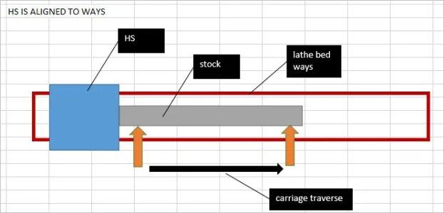
@Degen is heading straight into the alignment process biased somewhat by his earlier stated preference for using a perfect test bar. Which many of us now think prolly only exists for a short while (if at all) and then expires! LOL! Regardless of whether or not we have a good test bar, I think ALL OF US agree that the bed must be "untwisted" (levelled) first! Otherwise we chase our tails eternally. I don't think @Degen is particularly interested in what happens to hypothetical measurements along the way.

My observation is that both of you are correct within the limits of your respective assumptions. My apologies in advance if any of that comes across as criticism. It is not intended that way. It's only MY personal perception of the discussion. Please understand that that perception is complimentary, not critical.

Meanwhile though, that crazy lunatic 
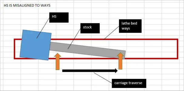
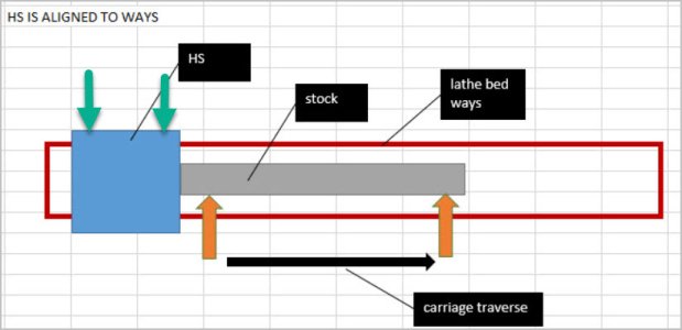
@Susquatch just wants to make a better tool to evaluate and potentially help correct head misalignment. That project of his assumes the bed has been corrected already.

Personally, I find all of the discussion very useful to me. On the other hand, other observers on the forum may be rolling their eyeballs at all of us!

Now for @StevSmar ...... Are you crazy? Why in the world would you introduce that potential black hole issue amidst the hurricanes taking place above? LOL! Just kidding! But seriously, if proper process is followed, the bed is already straight and therefore the test results purely relate to where the head points. But..... if as you suggest, if the bed is twisted in such a way that the test coupon becomes a perfect cylinder then I submit that everything cancels everything else, and the end results that the lathe produces works the way it should (produces a perfect cylinder), and we can get on with life. This is the outcome that @thestelster achieved earlier by deliberately twisting his lathe bed. The guy is a genius if you ask me...... But of course we must also acknowledge that he got there in a very unconventional way that even he would probably have preferred to avoid.

For my part, I would only say that your hypothetical result depends on a faulty process since your result is founded on incorrectly aligning the bed before going to the next step with the collar bar. Like you, I confess that I cannot easily get my head around what it takes to get that result though. I think it's probably some form of Helical bed shape that maintains the spacial equidistance of both rails from the central axis of the spindle in a coordinate system that is referenced to the saddle. But frankly, that's about as much neural power as I want to invest in the question....... (Insert image of a disoriented big old crazy hairy abominal snowman who just got off of a suicidal circus ride).

A few other points. 
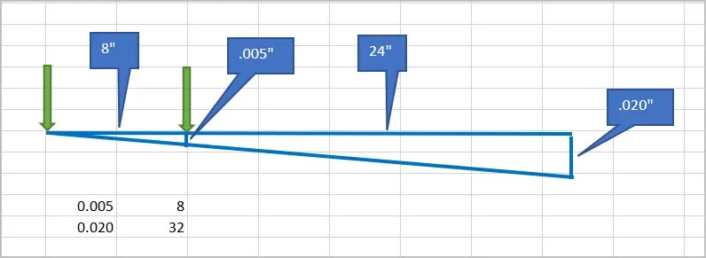
@PeterT - your analysis of the long coupon is exactly why I want to evaluate longer lengths. The longer the spacing, the better the resolution of the alignment measurement. Of course, there are two new problems that arise - bar droop due to gravity and deflection due to cutting forces. I have ideas about how to deal with those, but they require real world testing. I believe I can calculate them to some extent so I know roughly what they should be. But the variables are such that I think it requires real world calibration testing to be reliable enough to satisfy the intended purpose. That discussion belongs over in my other thread.
 
Last edited:

PeterT

Ultra Member
Premium Member
@Susquatch you will notice in my post I did not make any reference to a test bar. That was by intent. As you say my discussion is purely confined to lathe geometry. Specifically cause & effect of varying only one variable (HS yaw axis relative to lathe bed), just to keep the example as simple as possible. In the real world if your HS was similarly yawed & you turned down a collar bar, your coupon should yield the exact same dimensions, two diameters 0.030" different (notwithstanding cutting forces, droop, heat or any other related issues).

I provided a real world explanation of how this can occur (offshore machines with bolt on HS). I sketched out the underlying calculation methodology (simple triangle math). I plugged in what could be typical numbers in order to convey the relative numerical significance on this singular misalignment mode alone (0.005” of set screw yaw yields .030” diameter difference on a 24” collar bar). The point of this was to illustrate that HS alignment exists & is not an issue to dust under the rug. It is as important, if not more important, than twisting the bed (within practical limits).

Let’s call the aforementioned HS yaw misalignment mode A. Now I could have flipped the coin again & started down a different path. I could assume that mode A does not exist (the HS/spindle is perfectly aligned) and let’s examine mode B in isolation which represents lathe bed twist effect only. That is to say we mean to understand how much collar bar taper effect would be observed by jacking the TS feet by some defined amount. We will get to mode B, that’s what my CAD model discussion was about.

These 2 potential misalignment modes, A&B, both independently feed the resultant observed taper effect. So whether we discuss A first & B second or vise-versa doesn’t really matter. Ultimately they both need to be understood to assess their relative contribution to taper cutting problem. The issue is we cannot pretend A doesn’t exist & only focus on B. Or if we do, the conclusions will be incomplete & potentially erroneous. Maybe I am misunderstanding @Degen but he seems to be in this camp.

Similarly, it may well be that A&B serve to cancel one another in some special circumstance. I mentioned this myself early on & might be what @StevSmar is referring to. This possibility shouldn’t come as any surprise because A&B are independent to one another. For example think of A&B as vectors. At some point in they happen to become equal & opposing, therefore zero one another. But knowing that A&B happen to randomly null does not tell you anything about A or B individually. The anomaly might be interesting quirk, but it would be way more useful to have a deeper understanding of A & B on their own because now meaningful results could be determined for any permutation of A&B… including the point at which they may cancel if that’s of particular interest.

So the time will come to layer in additional considerations, complexities & misalignment modes. But right now do we agree on mode A? If not, why?
 

Dabbler

ersatz engineer
I think I should add that there are two separate components to all of this. The theoretical, which teaches us what to look for and understand what is happening when we change the situation by jacking, adjusting the head or other intervention.

My primary interest is the pragmatic side. Your head can be off, and your bed is twisted, the veeways are worn, or whatever. For me as long as you get a 'sorta cylinder' within reasonable accuracy and repeatability, then I'm good.

Real lathe leveling is successive: you 'level' the bed, you align the headstock, you align the tailstock - check it with the two collar test. Then you start all over again, starting with a subtle change to the lathe bed.

A few lathes I've worked on were beyond fixing, and some had very uneven lathe bed wear. As long as you know what you have, you can still live with it, and compensate for the shortcomings. Much like compensating for a lightly built late and parting off - there are things you can do to make it work.
 
@PeterT, its not about being one camp or the other. Its about ensuring you don't chase yourself silly when doing an initial set up. Your method works, not questioning that. The problem stems in the sequence. The less steps and re-set up the better.

Stable base point for measurement. This is a non-twisted base. After that whatever method and sequence floats your boat works. Your method is valid.

Now as to this chinese lathes being misaligned from the factory, I honestly think not (badly at least) as they do build to a spec. I think the mis-alignment comes during shipping and handling. Again light duty and not having the same clamping strength as heavier units.

Even then a proper setup and check is recommended.

I speak from personal experience that I had the head of my mill move along with the vise when a bit grabbed in some aluminum (overly aggressive cut) in addition moving the block in the vise.

That is a total of 7 clamping points allowing movement (and yes they are all torqued correctly) before the 2hp motor stalled.
 

Susquatch

Ultra Member
Administrator
Moderator
Premium Member
@Susquatch you will notice in my post I did not make any reference to a test bar. That was by intent. As you say my discussion is purely confined to lathe geometry. Specifically cause & effect of varying only one variable (HS yaw axis relative to lathe bed), just to keep the example as simple as possible. In the real world if your HS was similarly yawed & you turned down a collar bar, your coupon should yield the exact same dimensions, two diameters 0.030" different (notwithstanding cutting forces, droop, heat or any other related issues).

Not sure where you are going with this Peter. I didn't argue with any points that you have made. For the sake of clarity, I'll respond to each of your paragraphs one at a time.

I provided a real world explanation of how this can occur (offshore machines with bolt on HS). I sketched out the underlying calculation methodology (simple triangle math). I plugged in what could be typical numbers in order to convey the relative numerical significance on this singular misalignment mode alone (0.005” of set screw yaw yields .030” diameter difference on a 24” collar bar). The point of this was to illustrate that HS alignment exists & is not an issue to dust under the rug. It is as important, if not more important, than twisting the bed (within practical limits).

Agreed.

Let’s call the aforementioned HS yaw misalignment mode A. Now I could have flipped the coin again & started down a different path. I could assume that mode A does not exist (the HS/spindle is perfectly aligned) and let’s examine mode B in isolation which represents lathe bed twist effect only. That is to say we mean to understand how much collar bar taper effect would be observed by jacking the TS feet by some defined amount. We will get to mode B, that’s what my CAD model discussion was about.

Agreed.

These 2 potential misalignment modes, A&B, both independently feed the resultant observed taper effect. So whether we discuss A first & B second or vise-versa doesn’t really matter. Ultimately they both need to be understood to assess their relative contribution to taper cutting problem.

Agreed

The issue is we cannot pretend A doesn’t exist & only focus on B. Or if we do, the conclusions will be incomplete & potentially erroneous. Maybe I am misunderstanding @Degen but he seems to be in this camp.

I agree. But I don't think @Degen is in a different camp. That's because he hasn't embraced your assumptions. He has his own assumptions. In fact, I believe he totally agrees with you. But he is busy aligning his lathe while you are busy validating your measurement assumptions. I know that sounds silly, but I think all these perspectives are equally valid.

Similarly, it may well be that A&B serve to cancel one another in some special circumstance.

Yup, they certainly could.

I mentioned this myself early on & might be what @StevSmar is referring to.

Maybe you did, but I either missed it or forgot about it.

This possibility shouldn’t come as any surprise because A&B are independent to one another. For example think of A&B as vectors. At some point in they happen to become equal & opposing, therefore zero one another. But knowing that A&B happen to randomly null does not tell you anything about A or B individually.

Yup, it only tells you about A & B at that one particular point. Unless you have the bed Helix I suggested. In that case, I believe it is possible to have A & B cancel each other out at all positions. That's why I feel dizzy...... LOL. To be serious though, it's a ridiculous supposition that could never work in the real world. Hence all my fun with @StevSmar .

The anomaly might be interesting quirk, but it would be way more useful to have a deeper understanding of A & B on their own because now meaningful results could be determined for any permutation of A&B… including the point at which they may cancel if that’s of particular interest.

I agree again. However, I think it's a largely academic undertaking IF the bed is levelled before everything else is done. I think that is why @Degen insists on levelling the bed first.

And of course you frequently make that assumption too so I don't think we can fault him for that

So the time will come to layer in additional considerations, complexities & misalignment modes. But right now do we agree on mode A? If not, why?

We totally agree. Did I ever say we didn't?
 

Susquatch

Ultra Member
Administrator
Moderator
Premium Member
I think I should add that there are two separate components to all of this. The theoretical, which teaches us what to look for and understand what is happening when we change the situation by jacking, adjusting the head or other intervention.

My primary interest is the pragmatic side. Your head can be off, and your bed is twisted, the veeways are worn, or whatever. For me as long as you get a 'sorta cylinder' within reasonable accuracy and repeatability, then I'm good.

Real lathe leveling is successive: you 'level' the bed, you align the headstock, you align the tailstock - check it with the two collar test. Then you start all over again, starting with a subtle change to the lathe bed.

A few lathes I've worked on were beyond fixing, and some had very uneven lathe bed wear. As long as you know what you have, you can still live with it, and compensate for the shortcomings. Much like compensating for a lightly built late and parting off - there are things you can do to make it work.

I think that a great way to separate the view points here. Theory vs pragmatic.

You make another very important point though. The fact is that a good job of aligning a lathe will not likely be two steps. If you level the bed and then align the head, you probably screwed up the bed level. So ya, you probably have to accept that it will be several iterations before you get it "good enough".
 
Top