• Scam Alert. Members are reminded to NOT send money to buy anything. Don't buy things remote and have it shipped - go get it yourself, pay in person, and take your equipment with you. Scammers have burned people on this forum. Urgency, secrecy, excuses, selling for friend, newish members, FUD, are RED FLAGS. A video conference call is not adequate assurance. Face to face interactions are required. Please report suspicions to the forum admins. Stay Safe - anyone can get scammed.

What's this 9.5" long Test bar telling me?

Susquatch

Ultra Member
Administrator
Moderator
Premium Member
@PeterT - I apologize for my attempt at humour. I get myself in trouble that way all the time.

You made me laugh by suggesting that someone like me with an entire career in R&D didn't understand eliminating variables in an experiment. I simply couldn't resist throwing it back at you. But it seems to have degenerated into an argument. I'm sorry for that. It was not my intent.

The problem with assuming that the head/spindle is in perfect alignment with the bed is that this scenario cannot reasonably produce a reading that high. The moment of area (stiffness) of your ladder is simply too great to allow it to bend that much - especially not in the fore aft direction. There has to be another explanation.

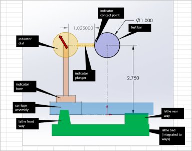
In your last reply, you refer back to the OPs question. So I'm no longer sure where you are really going with this question of yours. In the OPs case, we know the answer now. The bar that was being used to extend the axis of rotation was not concentric with the axis of rotation. After carefully reseating the test bar, much more reasonable results were obtained because the bar was now more closely aligned with the axis. That doesn't mean there is no misalignment - just that the misalignment is more reasonable. Also, I expect that a visit with Rudy to test the bar with a hands on explanation of what is going on will be of great benefit to Craig.

So I think that leaves only your hypothetical question which sticks to the original assumption of a perfect head bed alignment and asks what bed movement could produce such a relatively huge reading.

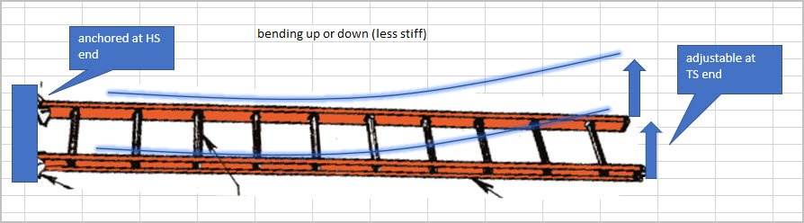
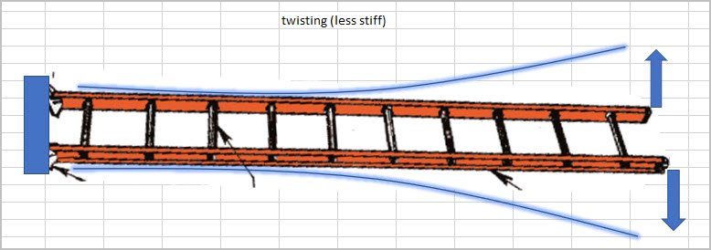
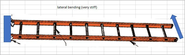
One answer (albeit quite unreasonable) is that the bed is bent in the horizontal plane away from the operator - like a curved railroad track on flat ground. It could also be warped up or down at the right as some of your examples show, but neither of those will move the needle that much without visible obvious twisting that would be obvious to the naked eye. Your drawings show that just fine and I believe that your simple math on that is correct.

So ya, how about a curved railroad track on flat ground......

I confess that I am reluctant to throw that out there because I know someone is gunna read that without the context and say something like "Are you crazy? No bed could ever bend like that!" And I would totally agree with them, and so would you. Nonetheless, given your assumptions it's the best answer I have. Change the assumptions and a perfectly reasonable answer pops out - the head is misaligned with the bed.
 
Last edited:
@PeterT I'm watching this thread looking at what is being said and the advice given and will add that one thing I've learned in engineering is "over thinking things, generally leads to overly complex and difficult long solutions".

Check level (twist) in the simplest most accurate form possible, your method is not simple and makes assumptions.

Check bow (are the ways straight).

Finally check headstock/spindle/chuck/collet system for alignment.

If checking the first using the last as reference, what error or errors are you actually measuring without making assumptions.

As a final note yes cast can wrap with age after machining, though this is rare as most modern cast machines are aged, rough machined, aged again and finally tolerance machined to ideally prevent that from happening. What does happen is forced clamping that removes a warp, is then machined and the wrap springs back in. In this case it is a manufacturing induced defect and this cased unless re-machined to tolerance are SOL.

For those that don't know aging is allowing material to settle to its most stress free state. In all materials a material is removed the distribution of internal stresses change in the material.
 

PeterT

Ultra Member
Premium Member
The problem with assuming that the head/spindle is in perfect alignment with the bed is that this scenario cannot reasonably produce a reading that high. The moment of area (stiffness) of your ladder is simply too great to allow it to bend that much - especially not in the fore aft direction. There has to be another explanation.
@thestelster provided us a real world example. A different lathe of course so apples & oranges to Craig. Maybe, arguably stiffer & more robust bed but I don't know the details of either. Anyways, his lathe was cutting a taper which was quantified by an initial cutting pass on his disc bar resulting in measured OD's of 1.9960" and 1.9983" spaced 5.25" apart. So that works out to (1.9983-1.9960)/2 = 0.00115" over 5.25". If we extrapolate that taper to the same test bar we would get 0.0021" over 9.75" which would be measured on the test bar side like Craigs setup in the fore-aft direction. But he inserted only 0.023" of shim to front right foot located 60-odd inches away when he removed the taper to nil.

Now how far adding more shims to achieve more even taper twist is another discussion. There has to be limits but lathe dependent. So point-1: the stiffness of the ladder did in fact allow for this degree of deflection. One hears of substantially more foot jacking being employed on other lathe claims, but I haven't cataloged corresponding twist results.

Point-2: to my thinking, it doesn't matter if we start with a bed in twist condition, exhibited by 0.002" taper remediate it to 0.000" purely by adding 0.023" foot shim. Or if we start with zero bed twist condition (corresponding to hypothetical model), insert 0.023 shim & observe the same 0.002" deflection on a test bar. I cant think of good reasons why these induced conditions are not reversible. Well actually I can, long term settling as mentioned. But that occurs over a extended time span, but neglect that for now.
 

Susquatch

Ultra Member
Administrator
Moderator
Premium Member
@thestelster provided us a real world example. A different lathe of course so apples & oranges to Craig. Maybe, arguably stiffer & more robust bed but I don't know the details of either. Anyways, his lathe was cutting a taper which was quantified by an initial cutting pass on his disc bar resulting in measured OD's of 1.9960" and 1.9983" spaced 5.25" apart. So that works out to (1.9983-1.9960)/2 = 0.00115" over 5.25". If we extrapolate that taper to the same test bar we would get 0.0021" over 9.75" which would be measured on the test bar side like Craigs setup in the fore-aft direction. But he inserted only 0.023" of shim to front right foot located 60-odd inches away when he removed the taper to nil.

Now how far adding more shims to achieve more even taper twist is another discussion. There has to be limits but lathe dependent. So point-1: the stiffness of the ladder did in fact allow for this degree of deflection. One hears of substantially more foot jacking being employed on other lathe claims, but I haven't cataloged corresponding twist results.

Point-2: to my thinking, it doesn't matter if we start with a bed in twist condition, exhibited by 0.002" taper remediate it to 0.000" purely by adding 0.023" foot shim. Or if we start with zero bed twist condition (corresponding to hypothetical model), insert 0.023 shim & observe the same 0.002" deflection on a test bar. I cant think of good reasons why these induced conditions are not reversible. Well actually I can, long term settling as mentioned. But that occurs over a extended time span, but neglect that for now.

Peter, I confess I am confused. I know it must be my fault somehow, and I have tried to figure out how. But I can't. I guess I am good at complicated math and science but not as good as I'd like to be with the soft people stuff.

When I talked about the ladder being too stiff, I was not talking twist, I was talking curved railroad tracks. Twisting a bed torsionally is WAY easier than curving it like a railway track. And I was not talking a few thou, I was talking about the 55 thou that you inferred to in post 53. Even then, you said it was not credible - and I wholeheartedly agree with that.

The fact is that I totally accept @thestelster's results and I even told him so earlier. So I have no idea why you feel compelled to use that as evidence for an error in what I said.
 

PeterT

Ultra Member
Premium Member
@Susquatch miscommunication between us again. I will keep persevering if you are game. More words & more pictures!

Regarding your railroad track analogy where the bed is twisted only in the horizontal plane, I think we can safely put that on the shelf. I didn't show it as one of the distortion modes for different reasons but I agree with you 100%. Using the same ladder frame analogy, the bed way is much stiffer in this mode. As opposed to jacking the TS ends up or down, together or opposed, resulting in the various distortion modes I sketched. And seems to me horizontal twist would be a highly unlikely factory defect.

The .055" I referenced in post #53 was my own gut check calculation to determine how much the bed would have to be distorted (bent vertically upward) such that an indicator registered on the test bar would indicate 0.003" needle deflection by that distortion mode effect alone. By effect I mean this: the indicator plunger is riding from position A to position B down the cylinder bar in all of our evaluation cases. Position A is zeroed at the HS end at 9:00 when viewed from TS. Position B is wherever it ends up & whatever the dial tells us. In bowed up mode it migrates somewhere towards in the northern hemisphere of the circular section bar because the indicator is carried by the carriage and the carriage is simply following the bed way profile. But because the resultant 0.055" of required bed rise at bar end position is a crazy high amount, I dismissed the entire notion as something not right. Why did I choose this seemingly impractical 'bed bowed up' mode? Because it was easier to spot calculate and I wanted to focus on the inconvenient aspect of the test hardware. The test bar is circular section which introduces this 'riding up or down' issue whenever there is any vertical alteration to bed ways & unfortunately this factors into the indicator reading like it or not. A better way of interpreting this outcome is pure bowed up or bowed down (same thing) is relatively insignificant for any normal condition lathe. Just like we determined that cantilever test bar droop is relatively insignificant. But we can only make these statements when we have a number staring at us with lots of zeros behind the decimal, so I felt compelled to do the calculation. Turns out its actually quite significant in twist mode, but I'm getting ahead of myself.

I've been working on another approach. A simplified 2D CAD model that can accept these various distortion modes as inputs & display resultant dimensions as an indicator would display. So I'm going to end it here (loud crowd cheer) & start a new post called CAD model lathe distortion or something along those lines. TBC
 

Attachments

  • SNAG-2022-06-04 12.53.24 AM.jpg
    SNAG-2022-06-04 12.53.24 AM.jpg
    63.1 KB · Views: 2
  • SNAG-2022-06-04 12.53.32 AM.jpg
    SNAG-2022-06-04 12.53.32 AM.jpg
    52.9 KB · Views: 2
  • SNAG-2022-06-04 12.53.54 AM.jpg
    SNAG-2022-06-04 12.53.54 AM.jpg
    45.2 KB · Views: 2
Last edited:

Susquatch

Ultra Member
Administrator
Moderator
Premium Member
@Susquatch miscommunication between us again. I will keep persevering if you are game. More words & more pictures!

Regarding your railroad track analogy where the bed is twisted only in the horizontal plane, I think we can safely put that on the shelf. I didn't show it as one of the distortion modes for different reasons but I agree with you 100%. Using the same ladder frame analogy, the bed way is much stiffer in this mode. As opposed to jacking the TS ends up or down, together or opposed, resulting in the various distortion modes I sketched. And seems to me horizontal twist would be a highly unlikely factory defect.

The .055" I referenced in post #53 was my own gut check calculation to determine how much the bed would have to be distorted (bent vertically upward) such that an indicator registered on the test bar would indicate 0.003" needle deflection by that distortion mode effect alone. By effect I mean this: the indicator plunger is riding from position A to position B down the cylinder bar in all of our evaluation cases. Position A is zeroed at the HS end at 9:00 when viewed from TS. Position B is wherever it ends up & whatever the dial tells us. In bowed up mode it migrates somewhere towards in the northern hemisphere of the circular section bar because the indicator is carried by the carriage and the carriage is simply following the bed way profile. But because the resultant 0.055" of required bed rise at bar end position is a crazy high amount, I dismissed the entire notion as something not right. Why did I choose this seemingly impractical 'bed bowed up' mode? Because it was easier to spot calculate and I wanted to focus on the inconvenient aspect of the test hardware. The test bar is circular section which introduces this 'riding up or down' issue whenever there is any vertical alteration to bed ways & unfortunately this factors into the indicator reading like it or not. A better way of interpreting this outcome is pure bowed up or bowed down (same thing) is relatively insignificant for any normal condition lathe. Just like we determined that cantilever test bar droop is relatively insignificant. But we can only make these statements when we have a number staring at us with lots of zeros behind the decimal, so I felt compelled to do the calculation. Turns out its actually quite significant in twist mode, but I'm getting ahead of myself.

I've been working on another approach. A simplified 2D CAD model that can accept these various distortion modes as inputs & display resultant dimensions as an indicator would display. So I'm going to end it here (loud crowd cheer) & start a new post called CAD model lathe distortion or something along those lines. TBC

There is a lot of water under the ladder here - so to speak.

I suspect one of the sources of miscommunication is the question itself. Perhaps it has morphed a bit as the situation got analysed. Or perhaps I (and a few others) never really understood what you were asking.

Could you repeat the revised or original question that you are asking as clearly as you can given all that's been said?

I'll be out planting corn all day today, so my apologies in advance.

If it's appropriate, perhaps that is best done on your new thread.
 
Last edited:

Susquatch

Ultra Member
Administrator
Moderator
Premium Member
Just like we determined that cantilever test bar droop is relatively insignificant.

Maybe you determined that, but I didn't.

I think that test bar droop is very significant for long test bars. And, I think long test bars are advantageous for at least two reasons.

1. They magnify the alignment error which makes it easier to measure and easier to determine the best adjustment.

2. They allow the operator to evaluate bed wear and alignment along a longer section of the bed.

But since bar sag or droop becomes significant at longer lengths, the droop must be evaluated and taken into account in the analysis.
 

PeterT

Ultra Member
Premium Member
Re bar droop, hold that thought. I am in complete agreement. This time I'm guilty of poor word choice. I didn't say ignore it, I said relatively insignificant. But what I failed to say was relative to a particular indicator orientation. Hopefully this will make more sense when the time comes.
 

YYCHM

(Craig)
Premium Member
Spent the better part of this morning at @RobinHood 's shop measuring up my test bar (Thanks Rudy).

Rudy has a big precision granite surface plate, precision matched v-blocks and instrumentation that measure to 0.00005".

The bar checked out very well. It's straight, round, and the taper is concentric with the barrel. My conclusion is that what I'm seeing with the bar mounted has to do with the spindle taper on my lathe and perhaps a slight headstock misalignment.
 

DPittman

Ultra Member
Premium Member
Spent the better part of this morning at @RobinHood 's shop measuring up my test bar (Thanks Rudy).

Rudy has a big precision granite surface plate, precision matched v-blocks and instrumentation that measure to 0.00005".

The bar checked out very well. It's straight, round, and the taper is concentric with the barrel. My conclusion is that what I'm seeing with the bar mounted has to do with the spindle taper on my lathe and perhaps a slight headstock misalignment.
Well I'd say that was time well spent eh?
 

PeterT

Ultra Member
Premium Member
Well just coincidentally I was picking away at my forthcoming post this rainy weekend. It was intending to be an elaboration on prior lathe alignment posts. Sounds kind of geeky but I made a simple CAD model to compute what an indicator 'should' read traversing a cylindrical test bar by introducing various (user defined) modes of lathe bed distortion via 3D dimensional inputs. It accounts for the indicator plunger riding up or down the bar OD slightly which factors into the reading.

However, a bad omen. Almost foretold by another member ( @Dabbler ) recent side conversation. I went to take some validation measurements of my Made in India test bars. Turns out they are not as good as I once thought they were. My longer one (~10 inches) the diameters still read pretty decent down the length ~ +/- 0.0001” diameter in either plane. But with MT engaged in spindle I now have +0.004” banana on the end which cannot be explained. I have mapped the bar from end to end with different rotation clock positions & there is no doubt. Perplexing is I pulled my notes of 4-ish years ago when purchased & this same measurement was just under 0.001” and quite linear slope (like 0.0005" at mid span) which made me suspect the MT axis vs the bar itself. A bow of 0.001" is still not great. What does one expect for $30.

So kind of took the wind out of my sails because a bowed ruler is rather a useless object for evaluating straight lines. Maybe stress relief? I need to make a @RobinHood appointment. I have come full circle on this because when I first looked for something like this bar they were kind of rare outside what seemed to be predominantly India. I saw one of Asian origin that had the feel of maybe Vertex but it was 3X more. I saw some USA ones that looked to be niche shop made, but few if any with MT end (only cylindrical) and more moola yet. I could grip a those in a collet but the idea was remove all the in between holding components for consistency. I recall a used one on Ebay that looked like it came out of a tool & die shop, maybe of Suburban quality, but it was a small fortune & showed corrosion. I didn't actually have high hopes when I ordered this one originally but told myself worst case the metal could be used for something. The cost isn't much different than a stick of 4140 at my local supplier & making something similar is not exactly trivial. When it turned out to be not too bad I thought lucky me. Now... I would say proceed with caution, might be the usual roll the dice outcome.

To Be Continued (maybe) LOL
 

Attachments

  • SNAG-2022-06-12 8.30.15 PM.jpg
    SNAG-2022-06-12 8.30.15 PM.jpg
    40.7 KB · Views: 5
  • SNAG-2022-06-12 8.31.27 PM.jpg
    SNAG-2022-06-12 8.31.27 PM.jpg
    69.6 KB · Views: 5
  • SNAG-2022-06-12 8.31.41 PM.jpg
    SNAG-2022-06-12 8.31.41 PM.jpg
    121.5 KB · Views: 4
  • SNAGIT.jpg
    SNAGIT.jpg
    39.1 KB · Views: 5

Tom Kitta

Ultra Member
Well just coincidentally I was picking away at my forthcoming post this rainy weekend. It was intending to be an elaboration on prior lathe alignment posts. Sounds kind of geeky but I made a simple CAD model to compute what an indicator 'should' read traversing a cylindrical test bar by introducing various (user defined) modes of lathe bed distortion via 3D dimensional inputs. It accounts for the indicator plunger riding up or down the bar OD slightly which factors into the reading.

However, a bad omen. Almost foretold by another member ( @Dabbler ) recent side conversation. I went to take some validation measurements of my Made in India test bars. Turns out they are not as good as I once thought they were. My longer one (~10 inches) the diameters still read pretty decent down the length ~ +/- 0.0001” diameter in either plane. But with MT engaged in spindle I now have +0.004” banana on the end which cannot be explained. I have mapped the bar from end to end with different rotation clock positions & there is no doubt. Perplexing is I pulled my notes of 4-ish years ago when purchased & this same measurement was just under 0.001” and quite linear slope (like 0.0005" at mid span) which made me suspect the MT axis vs the bar itself. A bow of 0.001" is still not great. What does one expect for $30.

So kind of took the wind out of my sails because a bowed ruler is rather a useless object for evaluating straight lines. Maybe stress relief? I need to make a @RobinHood appointment. I have come full circle on this because when I first looked for something like this bar they were kind of rare outside what seemed to be predominantly India. I saw one of Asian origin that had the feel of maybe Vertex but it was 3X more. I saw some USA ones that looked to be niche shop made, but few if any with MT end (only cylindrical) and more moola yet. I could grip a those in a collet but the idea was remove all the in between holding components for consistency. I recall a used one on Ebay that looked like it came out of a tool & die shop, maybe of Suburban quality, but it was a small fortune & showed corrosion. I didn't actually have high hopes when I ordered this one originally but told myself worst case the metal could be used for something. The cost isn't much different than a stick of 4140 at my local supplier & making something similar is not exactly trivial. When it turned out to be not too bad I thought lucky me. Now... I would say proceed with caution, might be the usual roll the dice outcome.

To Be Continued (maybe) LOL

Sorry it was me. I suggested the MT end may be off even if the bar is round.

It is difficult to make measuring tools. It is difficult to make them and then it is difficult to measure them to make sure they are OK.

Why would suburban tool ask over $1000 for cylinder square if it was easy to make?

Also India has a lot of very old machinery - I been there and seen it. Same for Pakistan. So getting something accurate is difficult even with the best intentions.
 

Dabbler

ersatz engineer
@Tom Kitta -- @PeterT and I were talking by phone at length about how these bars can (sometimes? often?) be quite useless. I have measured 2 directly and heard of 3 others. None were worth anything at all. @YYCHM test bar is an anomaly.

That being said the Suburban bar MT3/11.5", is very nice - concentric and straight to 2 tenths per foot. but it used to cost 1200$
 

PeterT

Ultra Member
Premium Member
Maybe we should start out with a finish ground bar & make the the MT arbor on the end! LOL.
The flat plane actually removes a source of indicator movement relating to the point drifting on either side of cylinder mid plane. In bed twist mode, its actually significant.
 

Attachments

  • SNAG-2022-06-13 7.02.48 PM.jpg
    SNAG-2022-06-13 7.02.48 PM.jpg
    29.9 KB · Views: 3

Susquatch

Ultra Member
Administrator
Moderator
Premium Member
Well just coincidentally I was picking away at my forthcoming post this rainy weekend. It was intending to be an elaboration on prior lathe alignment posts. Sounds kind of geeky but I made a simple CAD model to compute what an indicator 'should' read traversing a cylindrical test bar by introducing various (user defined) modes of lathe bed distortion via 3D dimensional inputs. It accounts for the indicator plunger riding up or down the bar OD slightly which factors into the reading.

However, a bad omen. Almost foretold by another member ( @Dabbler ) recent side conversation. I went to take some validation measurements of my Made in India test bars. Turns out they are not as good as I once thought they were. My longer one (~10 inches) the diameters still read pretty decent down the length ~ +/- 0.0001” diameter in either plane. But with MT engaged in spindle I now have +0.004” banana on the end which cannot be explained. I have mapped the bar from end to end with different rotation clock positions & there is no doubt. Perplexing is I pulled my notes of 4-ish years ago when purchased & this same measurement was just under 0.001” and quite linear slope (like 0.0005" at mid span) which made me suspect the MT axis vs the bar itself. A bow of 0.001" is still not great. What does one expect for $30.

So kind of took the wind out of my sails because a bowed ruler is rather a useless object for evaluating straight lines. Maybe stress relief? I need to make a @RobinHood appointment. I have come full circle on this because when I first looked for something like this bar they were kind of rare outside what seemed to be predominantly India. I saw one of Asian origin that had the feel of maybe Vertex but it was 3X more. I saw some USA ones that looked to be niche shop made, but few if any with MT end (only cylindrical) and more moola yet. I could grip a those in a collet but the idea was remove all the in between holding components for consistency. I recall a used one on Ebay that looked like it came out of a tool & die shop, maybe of Suburban quality, but it was a small fortune & showed corrosion. I didn't actually have high hopes when I ordered this one originally but told myself worst case the metal could be used for something. The cost isn't much different than a stick of 4140 at my local supplier & making something similar is not exactly trivial. When it turned out to be not too bad I thought lucky me. Now... I would say proceed with caution, might be the usual roll the dice outcome.

To Be Continued (maybe) LOL

Wow Peter, I wasn't expecting that.

I think you may have inadvertently saved me a lot of trouble. I do have an Indian bar that is scheduled to arrive here on Wednesday. I purchased it primarily so I could compare it to what I will call a two collar spindle alignment bar.

I confess that I was predisposed to favor the 2 collar bar because it can be cut to align with the spindle axis and although its not the same as the adapter issue you referred to above, anything that Plugs into something else without an adjustment introduces the chance of error. By cutting the two collar bar in the spindle of question, it becomes an extension of the spindle without any adapters.

However, enough members have suggested the spindle bar is a reliable tool so I felt it appropriate to test it myself. Seems like you have done that for me so I may have wasted my money - curiosity killed more that a cat. But of course, you are also right, at least I will have a nice bar of 4140 when it gets here.

What bothers me most about this is the thought of how many people have bought those bars and then jacked their lathes out of alignment because they thought the bar met specifications.

I look forward to hearing about your visit with @RobinHood.
 

PeterT

Ultra Member
Premium Member
I doubt I was hallucinating because I was staring at my original felt pen scribble of 0.0012" & that figure backs up my notes. Maybe they are like cheese & must be used before a Best Before Date lest they revert to a shiny banana.
 

Susquatch

Ultra Member
Administrator
Moderator
Premium Member
@Tom Kitta -- @PeterT and I were talking by phone at length about how these bars can (sometimes? often?) be quite useless. I have measured 2 directly and heard of 3 others. None were worth anything at all. @YYCHM test bar is an anomaly.

That being said the Suburban bar MT3/11.5", is very nice - concentric and straight to 2 tenths per foot. but it used to cost 1200$

Well, at least they are nice bars to make useful things out of.......
 

Susquatch

Ultra Member
Administrator
Moderator
Premium Member
There is one thought to this whole checking for accuracy.

If you are getting the result you want, why go digging for trouble?

Just asking for a friend ;)

Probably good advice for most people Degen. But we are all different in one way or another. A few guys (like me) just gotta poke the beehive......

Curiosity will prolly kill me some day - if old age doesn't get me first.
 
Last edited:
Top