The symptoms are a off though, as I'm getting within 5% over my whole speed range.
That does not make sense for an overflow problem. Is the get count function synced to the speed too? Or is it clock based? Or perhaps a bit of both?
The symptoms are a off though, as I'm getting within 5% over my whole speed range.
Ok, dug through the manual and the source somewhat more - the code sets QPOSMAX to 0x00ffffff - 24 bits of counter. That's 16M or so pulses per overflow, so that's not what's going on with my system. The hardware itself can go up to 31 bits. It looks like the choice of 24 is to match with floating point precision - more than that and you'd lose precision in the conversion to a 32 bit floating point number (23 bits of mantissa, plus the implied leading 1 bit).
So I'm on the slippage hypothesis. Breakfast is done, I just have to brave the ice storm for the trudge out 50' to the workshop.
So I'm on the slippage hypothesis.
I'm pretty sure it's a 32 bit counter and the variables are 32 bit. And it's sampling the count at 2Hz or every 500mS. However you have to factor in the large pulley diameter to small pulley diameter so the actual number of counts per spindle revolution is much larger than 2400.Ok, you've convinced me to check out the overflow handling in detail - yeah, my 600 step (2400 edges ) encoder spinning at ~1700 steps (6800 edges) per rev will overflow a 16 bit counter at as low as 8rpm when sampled every 2 seconds. The symptoms are a off though, as I'm getting within 5% over my whole speed range.
It's a 32 bit counter with a programmable overflow, set to 24 bits. The control code is all floating point, so the 24 bit limit makes sense.I'm pretty sure it's a 32 bit counter and the variables are 32 bit. And it's sampling the count at 2Hz or every 500mS. However you have to factor in the large pulley diameter to small pulley diameter so the actual number of counts per spindle revolution is much larger than 2400.
If you have taken that into account you might be out by the number of teeth you carved on the little pulley relative to the number of ribs on the back of the belt. I think guessing slippage is headed in the wrong direction.
It would appear to be a very poor approximator of the RPM, given that it has a hall effect sensor counting 4 times per revolution.
It is very slow to respond, and ramps oddly - I suspect it has a really shoddy software filter to generate the output. This is increasing my incentive to mount the new display and electronics directly in the lathe enclosure.Generally, I find Hall effect transducers to be very reliable. The wave form is especially immune to noise and miscounts. Is the gap too wide?
It is very slow to respond, and ramps oddly - I suspect it has a really shoddy software filter to generate the output. This is increasing my incentive to mount the new display and electronics directly in the lathe enclosure.
Edit: Oh and can you put the scope on the hall sensor feeding the lathe electronics?
I used my logic analyzer to count how many rising edges I have on the A signal in one revolution of the spindle, so that embeds the two radii. Multiplying that figure by 4 gives the number of edges the software is expecting.You said you had 600 lines for 2400 edges per rev. What's the diameter of the driven disk and what's the diameter of the driving pulley?

To me the diameter of the large pulley looks to be bigger than just over 2x the smaller one. So 600 lines on the encoder to get 1675 is 2.79. I suppose if the small pulley is 2" the big one could be 5.58". Hard to tell from the photo.I used my logic analyzer to count how many rising edges I have on the A signal in one revolution of the spindle, so that embeds the two radii. Multiplying that figure by 4 gives the number of edges the software is expecting.
Just wiring up that opto-sensor now, which I'll be able to hold in my toolpost easily enough. Then my scope should be able to get some RPM figures out for me.
Yes, I should be able to do that.Yes, I'd like to see this too.
You realize of course that the nut you used isn't really 1/2"-13 but actually 2mm pitch. 😛Yes, I should be able to do that.
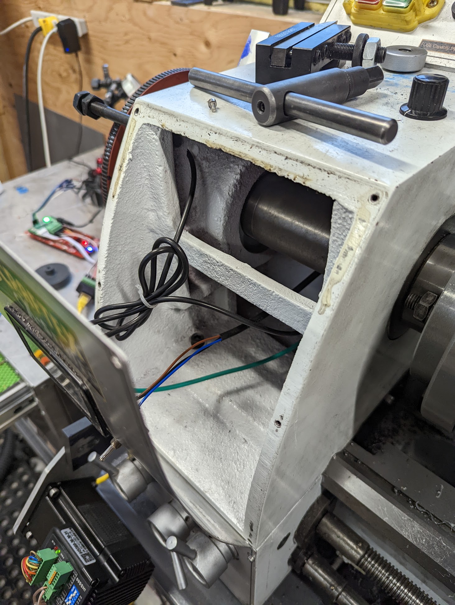
There's a little 8-bit Holtek HT48R30A hiding behind the panel. 10MHz job. Lots of empty, clean space behind there, so I'm pretty sure this is where my electronics will go.
Seeing if I can find the right Molex connector to adapt some leads onto the sensor wiring.
