• Scam Alert. Members are reminded to NOT send money to buy anything. Don't buy things remote and have it shipped - go get it yourself, pay in person, and take your equipment with you. Scammers have burned people on this forum. Urgency, secrecy, excuses, selling for friend, newish members, FUD, are RED FLAGS. A video conference call is not adequate assurance. Face to face interactions are required. Please report suspicions to the forum admins. Stay Safe - anyone can get scammed.

Weiss VM32 CNC Conversion

How the Fk did you manage to knock that all off in such a short time!

It's embarrassing you know.

Don't you have another shop to build or something?
Didn't I warn everyone that once @DavidR8 got back in the shop he'd make us all look very slow and pokey? At least he mucked up the pulley bore so that would set the rest of us back about 2 weeks while it will probably set him back one day.

I on the other hand did power up my mill today and the home all still works. Then I went back in and played some more with the 3D printer...
If only I had a CNC mill to make one :D
 
Didn't I warn everyone that once @DavidR8 got back in the shop he'd make us all look very slow and pokey? At least he mucked up the pulley bore so that would set the rest of us back about 2 weeks while it will probably set him back one day.

I on the other hand did power up my mill today and the home all still works. Then I went back in and played some more with the 3D printer...
....... pretty sure that you were supposed to hobble him a little last time you were over there....... I will say though, swapping pulleys was absolutely brilliant. ;)
 
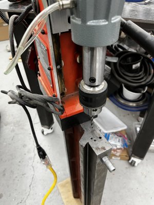
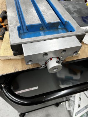
I was trying to figure out how I’d drill the end of the table to match the ball screw mount. Realized that I could stand the table on its end and use my mag drill.
Sketchy? Oh yeah.
IMG_1949.jpeg
Did it work? Like a charm.
IMG_1950.jpeg
Next task is to drill oil passages.
 
I will attempt to distract, should slow him down a bit.

Hey David, hows that shipping estimate coming along? ;-)

Did a quick check with UPS: 10lbs, Victoria to Ottawa about $50, wild guess on the size.

:D
 
Last edited:
I will attempt to distract, should slow him down a bit.

Hey David, hows that shipping estimate coming along? ;-)

Did a quick check with UPS: 10lbs, Victoria to Ottawa about $50, wild guess on the size.

:D
Bahahah I knew that was coming.
I’m rounding a bigger box as the one I had was only big enough for the control box but not the motor.
 
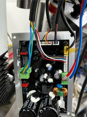
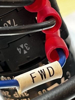
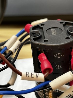
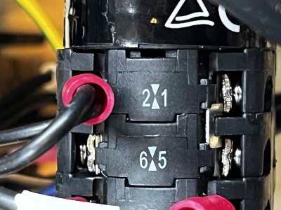
Sorry to be PITA, but before you pack an image of the FWD/REV wire terminal#'s that go to the control board would help me figure out how I'm going to interface this to my CNC setup.
Most likely a 4 pin connector with only 3 wires) probably blue, brown, black.

Thanks
 
Sorry to be PITA, but before you pack an image of the FWD/REV wire terminal#'s that go to the control board would help me figure out how I'm going to interface this to my CNC setup.
Most likely a 4 pin connector with only 3 wires) probably blue, brown, black.

Thanks
Thankfully I took pictures before I disconnected everything.
The four pin plug on the right highlighted in yellow comes from the fwd/rev switch. Blue, brown and black as you predicted.
IMG_1823.jpeg
 
Big day for the CNC conversion.
The X and Y tables had zero oil passages. Drilled and tapped passages for all, a total of five holes; one on each side of the Y axis and three on the X, one on the front, two on the back as the back is bisected by the hole where the Y axis lead screw attaches.
Plus cutting grooves into the bed ways so the oil can reach everywhere. Finished by stoning any burrs off.
Also had to reduce the height of the X axis ball screw attachment because it was proud of the bottom of the Y table. Just chucked it up in the 4-jaw and took a couple of hogging passes to create clearance.
No pics of any of that as I was knee deep in it.
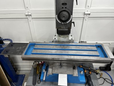
But the table is back on.
Next is oil passages for the Z axis.
IMG_1956.jpeg
 
I intended to add oil ports to the X and Y ball screws but there absolutely zero clearance for the oilers and no way to make it unless I hacked out 1/2” of cast iron in the case of the X axis and cut out a bunch of webs in the base for the Y.
I opted to pump the ball screws full of grease, the same as I do to the ball screws on my CNC router.
I hope to be able to fit an oiler to the Z axis ball screw but whether I can remains to be seen.
 
Last edited:
A bit of noodling. The upper right cap screw positions the mount in the right vertical orientation relative to the Y-axis table.
If I through drill the two bottom holes and put nuts on the inside that should be plenty secure.
If i could respectfully suggest,
You might be able to drill the holes oversize just enough that it will rotate and be flush and happy but still tighten good.
Maybe a few strokes with a round file
Then drill and drive in a couple dowel pins to keep it in place
That hard part is living with knowing its not perfect but it could be a short pathway to moving forward.
Best regards
Unfortunately they were very far off the mark. I would have had to drill the hole at least twice as large to make them fit.
 
Back
Top