-
Scam Alert. Members are reminded to NOT send money to buy anything. Don't buy things remote and have it shipped - go get it yourself, pay in person, and take your equipment with you. Scammers have burned people on this forum. Urgency, secrecy, excuses, selling for friend, newish members, FUD, are RED FLAGS. A video conference call is not adequate assurance. Face to face interactions are required. Please report suspicions to the forum admins. Stay Safe - anyone can get scammed.
-
Several Regions have held meetups already, but others are being planned or are evaluating the interest. The Calgary Area Meetup is set for Saturday July 12th at 10am. The signup thread is here! Arbutus has also explored interest in a Fraser Valley meetup but it seems members either missed his thread or had other plans. Let him know if you are interested in a meetup later in the year by posting here! Slowpoke is trying to pull together an Ottawa area meetup later this summer. No date has been selected yet, so let him know if you are interested here! We are not aware of any other meetups being planned this year. If you are interested in doing something in your area, let everyone know and make it happen! Meetups are a great way to make new machining friends and get hands on help in your area. Don’t be shy, sign up and come, or plan your own meetup!
You are using an out of date browser. It may not display this or other websites correctly.
You should upgrade or use an alternative browser.
You should upgrade or use an alternative browser.
Weiss VM32 CNC Conversion
- Thread starter David
- Start date
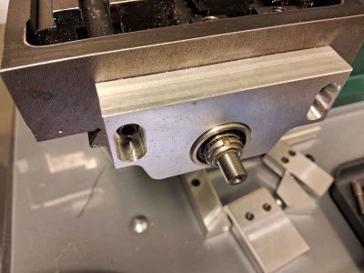
That's actually the right end of the table, the end where the servo will go. The smaller diameter is for the coupler, the larger for the bearing. The other end has a similar mount but the end of the ball screw has a nut to secure it.Dave, it looks good to me.
Just to confirm, your stepper (servo) is on the left side of the table? The right side is just the support for the non driven side of the ball screw?
How do they secure the ballscrew on the right side?
Ok, that makes more sense. It looks good to me, but I would wait for a few thumbs up from some real machinists. Too expensive to mess up. Sleep on it.
For what it is worth, back in the day I used a mini lathe on my ball screws with no problems. I used super thick heat shrink on them to protect them from the chuck.
For what it is worth, back in the day I used a mini lathe on my ball screws with no problems. I used super thick heat shrink on them to protect them from the chuck.
My biggest concern is actually getting the double ball screw nuts off without screwing them up.Ok, that makes more sense. It looks good to me, but I would wait for a few thumbs up from some real machinists. Too expensive to mess up. Sleep on it.
For what it is worth, back in the day I used a mini lathe on my ball screws with no problems. I used super thick heat shrink on them to protect them from the chuck.
I'm kinda hoping it will have enough length to go through the headstock and leave the nut on. But that's probably a fool errand.
Take a look at post 27 above. The center picture.
Find a piece of tubing the same diameter as the ballscrew. Over a nice big drop cloth, thread the ballscrew out carefully and insert the tubing to hold the balls in place. Make sure to insert the tube as you unscrew the ball screw. Do your work. Clean everything up and reverse the procedure. (Hopefully you do not need the drop cloth.....but I would not chance it.)
Don't leave the nuts on for the machining.
Edit: Thinking back on this I think the tube was actually smaller than the ballscrew. It was a loose fit. I can go measure if you need me to.
Last edited:
Yeah I figured I'd need to take them off. Thanks for the tip. I may machine up a retaining rod. I assume whatever I end up with needs to be the minor diameter of the ball screw?Take a look at post 27 above. The center picture.
Find a piece of tubing the same diameter as the ballscrew. Over a nice big drop cloth, thread the ballscrew out carefully and insert the tubing to hold the balls in place. Make sure to insert the tube as you unscrew the ball screw. Do your work. Clean everything up and reverse the procedure. (Hopefully you do not need the drop cloth.....but I would not chance it.)
Don't leave the nuts on for the machining.
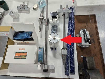
That's a pneumatic cylinder to make a pneumatic drawbar 🙂I was just back at some of the older posts of your kit. I didn't see it in any of the photos, but maybe there is a tube in the kit already for this purpose?
On another note....what is this item?View attachment 55610
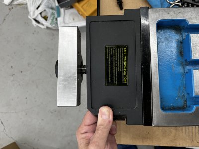
It’s possible, it would have to be pretty beefy to support the servo hanging off the end and resist the rotational forces.Is it feasible to make an extension? Might not be the most compact but it would work and you would not have to cut the ball screw down.
On further reflection the extension could go at the other end of the ball screw where there’s no servo hanging off.
On further reflection the extension could go at the other end of the ball screw where there’s no servo hanging off.
NICE!
I LIKE THAT!
With a little effort, that extension could become someplace to put your essential mill tools and other things that need a surface or assorted hangers to keep them handy!
Lots of beefy support there too. I like it!
+1 on the extension. The extension shouldn't need any more than 1/4 or 5/16 plate on the non servo end. It's only 5"ish but as @Susquatch says, it would also give more surface to pile tools on.
Interestingly enough, the distance is probably really close to the distance the old power feed is held away from the end of the table by the mounting bracket.+1 on the extension. The extension shouldn't need any more than 1/4 or 5/16 plate on the non servo end. It's only 5"ish but as @Susquatch says, it would also give more surface to pile tools on.
Pics to follow.
If you just miss, my headstock is a few inches shorter than yours, I think.enough length to go through the headstock and leave the nut on.
Sus and his horizontal surfaces 🙄NICE!
I LIKE THAT!
With a little effort, that extension could become someplace to put your essential mill tools and other things that need a surface or assorted hangers to keep them handy!
Lots of beefy support there too. I like it!
ChazzC
Ultra Member
It’s just his way to “organize” his tools.Sus and his horizontal surfaces 🙄


