-
Scam Alert. Members are reminded to NOT send money to buy anything. Don't buy things remote and have it shipped - go get it yourself, pay in person, and take your equipment with you. Scammers have burned people on this forum. Urgency, secrecy, excuses, selling for friend, newish members, FUD, are RED FLAGS. A video conference call is not adequate assurance. Face to face interactions are required. Please report suspicions to the forum admins. Stay Safe - anyone can get scammed.
-
Several Regions have held meetups already, but others are being planned or are evaluating the interest. The Calgary Area Meetup is set for Saturday July 12th at 10am. The signup thread is here! Arbutus has also explored interest in a Fraser Valley meetup but it seems members either missed his thread or had other plans. Let him know if you are interested in a meetup later in the year by posting here! Slowpoke is trying to pull together an Ottawa area meetup later this summer. No date has been selected yet, so let him know if you are interested here! We are not aware of any other meetups being planned this year. If you are interested in doing something in your area, let everyone know and make it happen! Meetups are a great way to make new machining friends and get hands on help in your area. Don’t be shy, sign up and come, or plan your own meetup!
You are using an out of date browser. It may not display this or other websites correctly.
You should upgrade or use an alternative browser.
You should upgrade or use an alternative browser.
Weiss VM32 CNC Conversion
- Thread starter David
- Start date
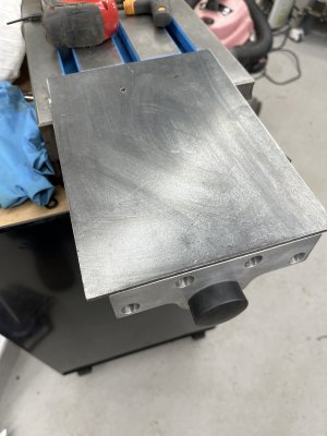
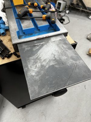
Sus and his horizontal surfaces 🙄
It’s just his way to “organize” his tools.
I tried to camouflage the real purpose for @DavidR8 but you guys saw right through me!
Nothing beats a horizontal surface for keeping things visible and ready to go!
The mill will be inside an enclosure so the potential for this to be tool storage is minimized 😀I tried to camouflage the real purpose for @DavidR8 but you guys saw right through me!
Nothing beats a horizontal surface for keeping things visible and ready to go!
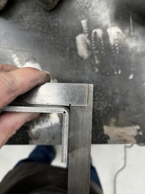
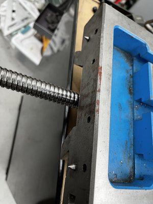
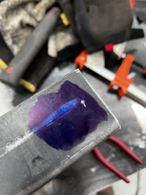
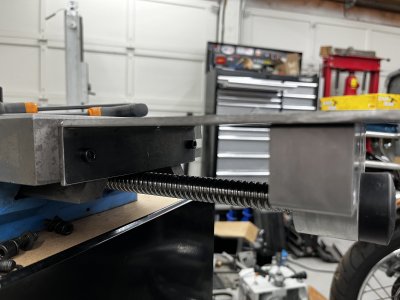
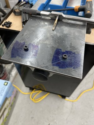
Now to mark the holes to secure the ball screw mount.
And done.
How the Fk did you manage to knock that all off in such a short time!
It's embarrassing you know.
Don't you have another shop to build or something?
I actually thought that took ages.How the Fk did you manage to knock that all off in such a short time!
It's embarrassing you know.
Don't you have another shop to build or something?
Maybe it’s because my shop is small so I don’t have to walk far to get things?
I honestly don’t know. Seemed like 2-1/2 hours from cutting the plate to installed is about right for me.
I haven’t powder coated it yet so it’s not done, done.
I haven’t powder coated it yet so it’s not done, done.
See, if you had milled that out of a solid chuck of cast iron or even steel, you would still be shopping for the stock or at least having fun making chips and you wouldn't need to paint it.
I hope you don't run out of things to do runnin around that shop at laser speed like that.....
I'd change your user name to RoadRunner, but you would just change it back..........
In the future it will be a cup 'o chips! 😀At least put a cup holder on it!
I like the idea of the shelf, but I think using plate to implement it might not be the best answer. If you plan on sticking with the plate it would be wise to add a front and back side plate to it.
You will see some flex the way it is set up now and that might load up your ballscrew nut as the ball screw flexs out of alignment.
You will see some flex the way it is set up now and that might load up your ballscrew nut as the ball screw flexs out of alignment.
Agreed. I’ll probably TIG some sides onto it before I finish it up.I like the idea of the shelf, but I think using plate to implement it might not be the best answer. If you plan on sticking with the plate it would be wise to add a front and back side plate to it.
You will see some flex the way it is set up now and that might load up your ballscrew nut as the ball screw flexs out of alignment.
Agreed. I’ll probably TIG some sides onto it before I finish it up.
Might be a good excuse to take a few more days on this project and mill something out of a block of metal so the rest of us don't feel so inept.....
140mower
Don
At our age we are all getting a little low in iron anyway..... 🙄In the future it will be a cup 'o chips! 😀
The new timing belt pulley for the servo motor arrived today. Motor spec sheets said 19.6mm shaft so I went looking for pulleys with 20mm bore.
Pulley bore is spot on, 20.1mm. Offer it up to the spindle and it's loose like a baggy sweater... mic the shaft and it's 18.89mm, almost 1mm smaller in diameter.
Pulley bore is spot on, 20.1mm. Offer it up to the spindle and it's loose like a baggy sweater... mic the shaft and it's 18.89mm, almost 1mm smaller in diameter.
140mower
Don
I see some of my luck might be rubbing off on you....... It's a tough path ahead. 🙄The new timing belt pulley for the servo motor arrived today. Motor spec sheets said 19.6mm shaft so I went looking for pulleys with 20mm bore.
Pulley bore is spot on, 20.1mm. Offer it up to the spindle and it's loose like a baggy sweater... mic the shaft and it's 18.89mm, almost 1mm smaller in diameter.
Well everyday is a learning day.
The motor drawing has the shaft at 19H6 which I thought was some offshore way of saying 19.6. In fact it's a tolerance as I'm sure most/many/all of you know.
So the shaft is 19mm nominal with an allowable tolerance of 19 - 19.036
The motor drawing has the shaft at 19H6 which I thought was some offshore way of saying 19.6. In fact it's a tolerance as I'm sure most/many/all of you know.
So the shaft is 19mm nominal with an allowable tolerance of 19 - 19.036
Unfortunately not. No big deal. At $10 the pulley was cheap enough to put in stock and chalk it up to learning.Is there enough meat to bore it past the keyway and then sleeve and rebore it?
What I take from that photo is @DavidR8 is trying to slip your mill into his back pocket (to take home) but you caught him with a photo so now he's pretending to measure something.A productive morning, and a happy @DavidR8 . He can moderate the picture (and this sentence?) out of existence if he doesn't like it ;-)
View attachment 55174

