TorontoBuilder
Sapientia et Doctrina Stabilitas
Are you going to 3D print first or go right to steel?
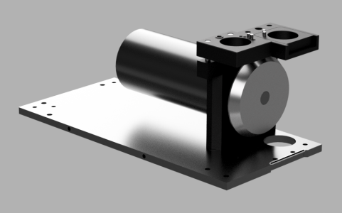
I assume the wheel is flipped to use the rear socket. I am usually very good at seeing things in my mind. But I haven't been able to see this one. Any orientation my mind sees doesn't work. Can you (or someone) do a Fusion model to see how that works up close and personal?
If as Ian suggests there are no flats on the shaft, and we have to flip the wheel all the time, I would want to grind flats in the shaft, or maybe there is some other approach.
I assume this is necessitated by the need to provide an adjustable Z? Could that be facilitated without flipping the wheel by a pocket and various inserts instead of a slide and inserts? Or maybe an adjustable Z slide......
Yes @Susquatch I'll test with 3D printed parts first.
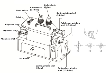
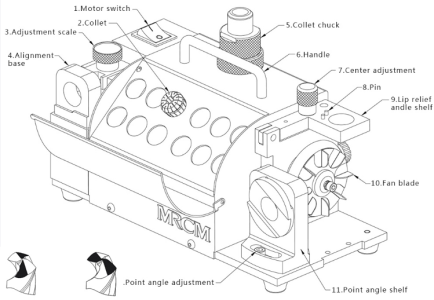
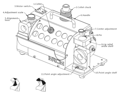
Think of my adaptation as just a variant of the standard MR-13D drill sharpener configuration with the grinding wheel in the standard orientation, widest section towards the motor mount. MRCM's nomenclature differs slightly from mine,
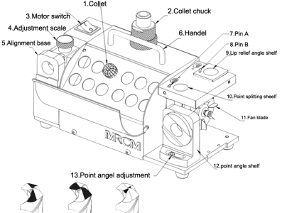
The tool block on the left is the web thinning, while the tool block on the right is point splitting. Not shown is the point angle grinding tool block.
You'd use this to grind all your drill bits in this configuration, there is little to adjust but it is fully adjustable. No wheel needs to be flipped or anything else as complicated as that. Just tweak the height of blocks A and B as your web diameter increases, or change the point angle to the desired setting and sharpen.
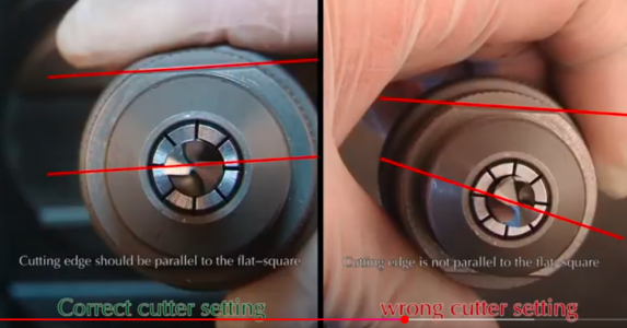
But if you wish to have an end mill sharpening session that you'd need to make further modifications to add 3 different tool blocks which copy those of the simplest design, the MR-X1 and you'd need to reverse the wheel. It is not intended as a simple process that allows user to swap between end mills and drill bits on the fly.
