• Scam Alert. Members are reminded to NOT send money to buy anything. Don't buy things remote and have it shipped - go get it yourself, pay in person, and take your equipment with you. Scammers have burned people on this forum. Urgency, secrecy, excuses, selling for friend, newish members, FUD, are RED FLAGS. A video conference call is not adequate assurance. Face to face interactions are required. Please report suspicions to the forum admins. Stay Safe - anyone can get scammed.

Tool Vevor Drill Bit Sharpener Improved

Tool
Here is a good article on drill bit geometry,

Thanks for providing web link. That's where I borrowed the end view 4-facet pictures I scribbled on in a previous post. I saved the PDF but couldn't remember where I got it. Of interest he mentions a 6-facet grind. There have also been articles that have countered some of his claims (or found a preferred manufacturing method that accomplishes the advantages of some of his recommendations). I don't know for a fact but I have a feeling the production machines & drill technology have advanced in CNC & some of the profiles reflect this: machine accuracy, repeatability, rigidity, RPM range, pecking routines, high discharge internal coolant ports, all kinds of carbides & other materials.. Whereas we are still kind of stuck in the manual machine mode from that perspective, but can utilize some of their table bones.
 
And just to throw this into the mix, turns out 'split point' is more of a generic term than I realized. There are different shades.

 
And just to throw this into the mix, turns out 'split point' is more of a generic term than I realized. There are different shades.


This fellow's arguments as to why he isn't a fan of split point drills in his shop actually strongly reinforces the whole point of the project to design a MR-13 grinder conversion.

A properly configured MR-13Duo machine can perform a proper web thinned split point grind, the fellow is just unaware of this fact. That we can mod an off the shelf mass produced fully equipped machine for under half the price of the typical clapped out incomplete dirty filthy used cutter grinders usually go for can put a well performing product in the hands of most serious hobby metal workers without breaking their budgets.

Or just the hands of a few who want to put in a little work. For myself I recognized almost immediately that this was the solution to a long term problem of mine. That I can convert it to sharpen end mills as well will just be a bonus.
 
And just to throw this into the mix, turns out 'split point' is more of a generic term than I realized. There are different shades.

My God. I watched it only because you posted it, and it was relatively short and to the point - so I gotta give him that. But quite frankly, I couldnt watch that and even come close to thinking he has any advice worth taking. His final words were "That, in a nutshell, is why I am not a fan of split point drill bits in my home shop".

Really? I'll say right out loud that I think split point drill bits work just great. Maybe there are better grinds out there, but I can't afford them let alone resharpen them. Nothing he said changes my view of that.

I really dislike self annnointed YouTube experts.

There was a good outcome from watching this video though. In my mind, I have been assigning Split Pointing into a subset of grinds that includes webthinning. But now I am forming the idea that split points are actually only one of many different kinds of web thinning grinds.
 
If he says that, he hasn't drilled enough holes with a drill motor. Or he's just plain crazy.

He actually does. It's at the very end of the video. If he had said that up front I wouldn't have wasted my time watching. But given the way he summed that up at the end, I believe it was the whole point of his video. Crazy sounds totally appropriate.
 
My God. I watched it only because you posted it, and it was relatively short and to the point - so I gotta give him that.
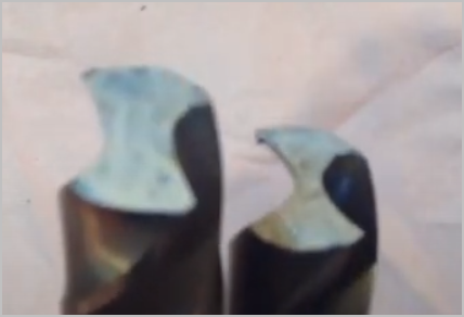
I should have provided my 'skip to time X:XX' so your eyeballs wouldn't melt LOL. I wasn't really interested in his opinion so much as I learned something new. The split point (left) or at least 'his' split point has a considerably larger center core, or shallower flute pockets however you want to define it compared to regular drill )right). That's done for rigidity & other reasons. But the implication is when you translate that thickness up to the tip, do the primary grind, you are going to have a much fatter dead zone core area. If left that way, undesirable. Which is WHY they split point. Now I took one of my so called split points & ground it straight like he did & it looks remarkably like my regular jobber. So he may be branding all split points the same when in fact they may vary among brands, materials & applications. I happen to know they do in fact vary, particularly carbide & carbide with cooling ports, but just trying to reframe why I mentioned this video at all.

2:52
1735948860511.png
 
I should have provided my 'skip to time X:XX' so your eyeballs wouldn't melt LOL. I wasn't really interested in his opinion so much as I learned something new. The split point (left) or at least 'his' split point has a considerably larger center core, or shallower flute pockets however you want to define it compared to regular drill )right). That's done for rigidity & other reasons. But the implication is when you translate that thickness up to the tip, do the primary grind, you are going to have a much fatter dead zone core area. If left that way, undesirable. Which is WHY they split point. Now I took one of my so called split points & ground it straight like he did & it looks remarkably like my regular jobber. So he may be branding all split points the same when in fact they may vary among brands, materials & applications. I happen to know they do in fact vary, particularly carbide & carbide with cooling ports, but just trying to reframe why I mentioned this video at all.

I hear you Peter. Lots to digest, lots to improve, and lots to gain with an improved drill grinder!
 
So I'd like to get a couple of owners of MR-13A machines to provide me with the following measurements to replace my bare azzed guesstimates with.

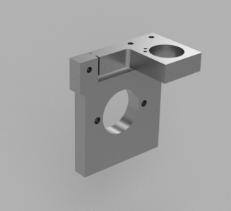
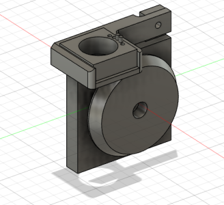
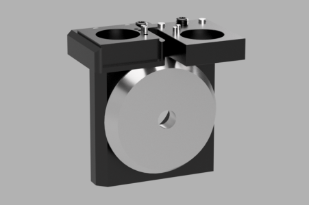
These is a rendering of the two parts in question.


1735957694044.png


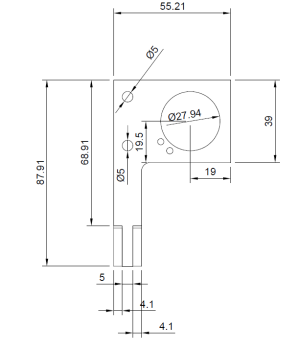
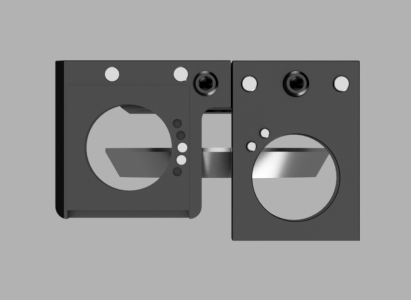
The image below is a plan view of the two parts looking from the front of the machine.


1735957478515.png


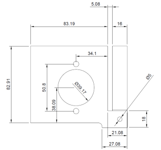
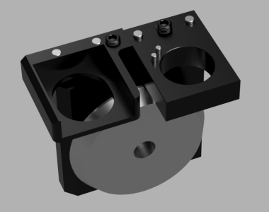
The image below is is from the back side of the vertical upright piece.

1735957762577.png


Don't do it for me, do it for the other John.
 
So I'd like to get a couple of owners of MR-13A machines to provide me with the following measurements to replace my bare azzed guesstimates with.

These is a rendering of the two parts in question.

Have you done that for the B version yet? Need me to do that?
 
So I'd like to get a couple of owners of MR-13A machines to provide me with the following measurements to replace my bare azzed guesstimates with.

These is a rendering of the two parts in question.


View attachment 57186


The image below is a plan view of the two parts looking from the front of the machine.


View attachment 57182

The image below is is from the back side of the vertical upright piece.

View attachment 57189

Don't do it for me, do it for the other John.
I'm working on it but it's getting late. Tell you tomorrow.
 
Okay, I've been looking at both the A and B model designs. It is clear to me that they designs are the way they are to make production as cheap as possible without the need for any complex machining operation.

The two machines I have measurements for have clear differences in the vertical plate thickness, and other areas, which I thought surprising. This piece is the main positional register for the shaft and grinding wheel. But that isn't really an issue.

My goal is to make a very precise multifunctional tool grinder, not just for drill bits but also for end mills ends. By selecting pivots to raise and lower the tool holder in an arc there is no simple direct reading of the depth of adjustment.

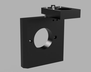
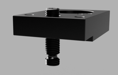
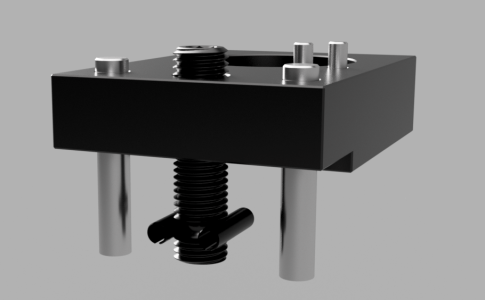
I propose to fix that by having each tool block adjust its vertical position by turning an 8mm grub screw. The screw will act as a jack to raise and lower the tool block, and two 6mm precision ground pins will serve to guide the block along the vertical plane without an rotation.

This method works by having the tool holder block threaded for the 8mm screw, while the vertical base plate has an 8mm clearance hole in which the screw sits and can revolve freely. In order to prevent the screw from being pulled from the base the end of the screw will have a 3mm retention groove machined around the circumference.

Meanwhile, the base will have two 3mm holes perpendicular to the screw and on the level of the 3mm groove in the screw. Two roll pins will be inserted into holes in the base, through the groove on either side of the screw, thus the screw will be prevented from retracting out of the base while still allowing the screw to be freely rotated.


duo test 2.PNG


duo test 4.PNG


duo test 3.PNG


The two tool blocks can then move independently from each other with a vertical adjustability of upwards of 5mm of travel, or be removed entirely and substituted with a different block for a different purpose. For instance split point block A could be substituted with split point block B which is offset x degrees from vertical
 
The vertical upright plate dimensions I have are two different thicknesses... so I wonder if there is a slight difference in the base hole locations. I doubt it but wonder.

The difference I have infringes on the sheet metal case by 2mm which I wont modify, so I;ll have to see how critical these are... or I may change the design to use a vertical motor mount that based on the thinner dimension. That will mean I cant use the insert for the 13B restricting my options.

But at least I'm ready to print up some mock parts

1736050626277.png


1736050971960.png
 
not just for drill bits but also for end mills ends.
Does Vevor (or any of the Chinese brands) make a similar machine that grinds end mills? I know these machines (13A and 13B) say drill bit/end mill sharpener but I thought the consensus was they only did drill bits? Have I missed something along the way?
 
Last edited:
I know these machines (13A and 13B) say drill bit/end mill sharpener but I thought the consensus was they only did drill bits? Have I missed something along the way?

There is some limited info that suggests that they will do end mills too, and there are also some collet holders for 2,3,4,6 flute tools too. I have some in my shopping cart right now.

I will order as soon as I figure out how to combine shipping. Same company, individual shipping for now. The cheap skate in me won't accept that.

I believe it can do end mills. But it will take some work to figure it out.
 
But at least I'm ready to print up some mock parts

Two questios:

20250105_111654.png


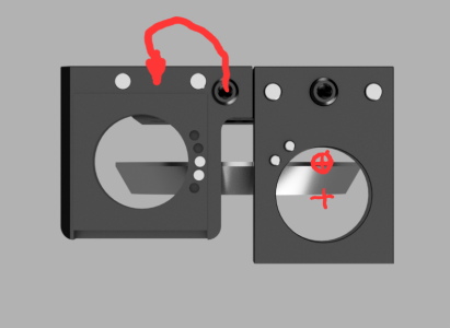
On the left side, would it be better to have the screw between the pins than off to the right? What drove that choice?

On the right side, why is the collet holder center so far away from the rear edge of the wheel? Help me understand the goal here.
 
Does Vevor (or any of the Chinese brands) make a similar machine that grinds end mills? I know these machines (13A and 13B) say drill bit/end mill sharpener but I thought the consensus was they only did drill bits? Have I missed something along the way?
The manufacturer makes a bunch of machines mostly based on this design that sharpen end mills.

Recognize this machine.. two extra fixtures and a dovetail slide and voila it sharpens end mills

 
Two questios:

View attachment 57253

On the left side, would it be better to have the screw between the pins than off to the right? What drove that choice?

On the right side, why is the collet holder center so far away from the rear edge of the wheel? Help me understand the goal here.

It would have been a better screw location @Susquatch , but I was trying to retain the same "insert" design to make it flexible for end mill grinding, and it did not leave enough material at that location. Here is the same parts without the insert

1736099281244.png


I may ditch that in favour of two swappable plates instead. It is just harder and more annoying to make the plates with an angled hole instead of angled insert.

As far as I can tell from all the measurements and videos and photos the A model does the point splitting using the front edge of the wheel rather than the back edge. I wasn't able to get the wheel projection on the A machines yet though to find exact projection of the A tool plate compared to the wheel

I do have the solution though. I'll put an insert type tool holder in the A tool plate location... and the normal non-insert in the B tool plate location because that is how the insert tool plate is installed on the end mill sharpener. The projection is exactly the same, because the grinding wheel is reverse with the wide flange on the outside for end mill sharoening.
 
Last edited:
As far as I can tell from all the measurements and videos and photos the A model does the point splitting using the front edge of the wheel rather than the back edge.

I see. Makes sense. You can only use the info you have. So how in the world do you grind a split point with the front edge? Must be more to it than we can see on line. Maybe when we get better projections it will all be clearer.
 
Last edited:
Back
Top