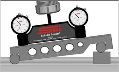
Speaking of milling heads that are difficult to tram: the Huron style ones are apparently the worst because it is hard (impossible?) to isolate the X and Y directions from one another because of the oblique mounting flange. This is where a calibrated tramming tool shines.
View attachment 18321
I'd be willing to place a beer wager that my three gauge triangle idea would make short work of that challenge.
But I truly hope I lose - I'd love the opportunity to get you beer silly! Especially if my gnarly gauge ends up half as twisted as I see it in my minds eye......