• Scam Alert. Members are reminded to NOT send money to buy anything. Don't buy things remote and have it shipped - go get it yourself, pay in person, and take your equipment with you. Scammers have burned people on this forum. Urgency, secrecy, excuses, selling for friend, newish members, FUD, are RED FLAGS. A video conference call is not adequate assurance. Face to face interactions are required. Please report suspicions to the forum admins. Stay Safe - anyone can get scammed.

Spindle square

Speaking of milling heads that are difficult to tram: the Huron style ones are apparently the worst because it is hard (impossible?) to isolate the X and Y directions from one another because of the oblique mounting flange. This is where a calibrated tramming tool shines.

View attachment 18321

I'd be willing to place a beer wager that my three gauge triangle idea would make short work of that challenge.

But I truly hope I lose - I'd love the opportunity to get you beer silly! Especially if my gnarly gauge ends up half as twisted as I see it in my minds eye......
 
Speaking of milling heads that are difficult to tram: the Huron style ones are apparently the worst because it is hard (impossible?) to isolate the X and Y directions from one another because of the oblique mounting flange. This is where a calibrated tramming tool shines.

View attachment 18321

Hard to tell what I'm really looking at there. Is that head really sitting on a round angular flange? And what are all those cranks, dials, switches, and knobs for? I'm thinking that thing would create some glorious times for us guys that like playing with a million adjustments!

Or is that really a space ship in disguise?
 
Is that head really sitting on a round angular flange? And what are all those cranks, dials, switches, and knobs for?

It is just a picture I grabbed of the internet - my dream manual machine if one ever came up for sale at a reasonable price.

Yes, it is siting on an angular flange and the whole head is on a swivel behind it.

The dials, cranks, switches and knobs are to control spindle speed, feeds, rapids, etc, both mechanically and electrically.

I probably misread at least one of your posts and did not catch that you were planning on making a tri-gauge tramming tool. Should be a fun project. For sure, once calibrated, it would be the fasted way of tramming a milling head in both X and Y concurrently.
 
Another application for a dual gage. Tramming to a sine bar reference. If the bar was along X, then I guess here you need reverse procedure - establish nod first & tilt second.
 

Attachments

  • SNAG-2021-11-16 10.35.41 PM.webp
    SNAG-2021-11-16 10.35.41 PM.webp
    11.1 KB · Views: 4
I probably misread at least one of your posts and did not catch that you were planning on making a tri-gauge tramming tool.

That would have been easy to do. I was carrying on two conversations at once. One with you and @PeterT where I was trying to understand your concerns about tramming nod with the spindle behind the bed, and another simultaneous conversation with @Brent H in the same thread about making a tri-gauge tool. Unless you were following the whole thread as opposed to just those with your user name in them, it would have been easy to miss as those posts very short compared to the books that you and Peter and I seem to like writing...... LOL!

If you skim back, you will see that I threw in the towel on the speed issue almost right away. Perhaps my initial poor attempt to have some fun with Brent wasn't as obvious as it could have been to everyone!

I like to learn. I like to help. And I like to have fun too!

FWIW, the idea of incorporating optical illusions into the tri-gauge fixture that I mentioned to Brent was really just another shot of humour aimed at you that arose out of the difficulty I had visualizing your concerns.

All is well that ends well!
 
Last edited:
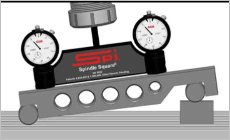
Another application for a dual gage. Tramming to a sine bar reference. If the bar was along X, then I guess here you need reverse procedure - establish nod first & tilt second.

I like the overall idea, it's a cool looking fixture and setup.

But I confess that I have no idea right now where or why anyone would want to do this....

Nonetheless, I have stored the concept into my cerebral archives as a potential solution to a problem I have not encountered yet......

Also, wouldn't this fixture work a bit better with the bars or balls built into the fixture itself and the balls shown here replaced by gauge blocks?
 
A question for all regarding spindle squares.

The tables on all 4 of my mills & drills are not perfect. And even if they were, the TSlots make calibrating a gauge or indicator difficult. I have always swung / swept the indicator tip backward to avoid damaging it.

But all this discussion about tramming has me wondering about what I will call a tram plate. Something like a precision ground plate that you set on the bed and then run your indicator (or tram tool once I make one) on that.

I'm thinking that perhaps a premium automotive brake rotor might be a great solution. They are typically ground to be ultra flat when new and they are not outrageously expensive for what you get.

However, I find myself wondering how well they would work on a mill table. How much would an oil film or a human hair or the one teeny tiny ding my stone didn't catch affect its usefulness?

Anyone have any experience or thoughts on this?
 
@Susquatch : Typically if you are tramming the head, you do it to a flat surface (like the vice) - not necessarily your mill table. If I want to tram to the table I will set up a parallel that spans a good distance (say an 8 or 10") and make sure the table is lightly stoned and wiped off. Set up the parallel in the direction you need to go such that it will span the table imperfections and give you a proper calibration.

The Sine bar, table etc can be used to set up the head at very accurate angles or a work piece. Tramming the head to the sine bar will give you that 30.01 degree of accuracy or better depending on you.

You can also tram with a matched set of 123 blocks etc.

Lots of different options

I'm paying close attention to the advice I got earlier from a certain sailor I know. Lots of ways to do it, so I'm just aiming for fast and easy. Preferably home made and faster and easier than whatever the rest of the crowd uses to increase the pride factor.

Was hoping to be able to make a sweep system to facilitate that. Blocks and parallels will work but still suffer the bump as the needles transition from open space to the gauge surface. I'm thinking here about the initial calibration effort. All the gauges need to be set to show the same measurement at the same place before they can be used in different places to show the difference. I thought a big circular plate like a disk brake rotor might do that job well and as bonus extend back behind the bed too. But that's just a guess.
 
I like the overall idea, it's a cool looking fixture and setup.
But I confess that I have no idea right now where or why anyone would want to do this....

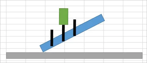
Picture any part that is long-ish with angled features that require milling/drilling/whatever. It is easier to rotate the head to the work axis vs angling the work to meet a perpendicular spindle axis. Particularly, headroom becomes diminished & more complex fixturing/clamping arrangement is required.

Or visualize replacing the left sketch blue part with a rotary table assembly. Now more complex parts can be machined in 4 axis independently. These would be very clunky if not impossible to accomplish with a head confined to 2 locked perpendicular axis.
 

Attachments

  • SNAG-11-17-2021 000.webp
    SNAG-11-17-2021 000.webp
    3.9 KB · Views: 1
  • SNAG-11-17-2021 001.webp
    SNAG-11-17-2021 001.webp
    4.6 KB · Views: 1
Picture any part that is long-ish with angled features that require milling/drilling/whatever. It is easier to rotate the head to the work axis vs angling the work to meet a perpendicular spindle axis. Particularly, headroom becomes diminished & more complex fixturing/clamping arrangement is required.

Or visualize replacing the left sketch blue part with a rotary table assembly. Now more complex parts can be machined in 4 axis independently. These would be very clunky if not impossible to accomplish with a head confined to 2 locked perpendicular axis.

I see! So this us all about tramming the head to cut on an angle VS the table.

I assume that usually means doing most of the cutting work using the Y-axis on the table..... And nod angle adjustments would use the X axis.
 
Hey @RobinHood, @PeterT, & @Brent H , & all those others following this thread. I had to go visit the doctor today and had some time to kill waiting for my turn in the torture room.....

I decided to spend some time looking to see if anyone had ever made a 3 gauge tram system. I didn't find one, but I did find these interesting ways of going about using two dials.

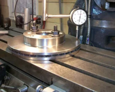
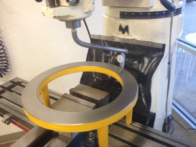
One is actually the brake rotor that I thought might work. Apparently someone else had the same idea. And it does work!

The other is a raised rotor that clears the vice. I really like that too! No need to remove the vise to tram the mill!

Tramming-a-Milling-Machine-Head.webp


FBM7DN9HT1M2SV6.jpg


I'm thinking that maybe three custom precision blocks under the rotor would work just fine.

Lots of room for that illusion I want so badly too...... LOL!
 
Jeeez you could make that raised rotor gizmo yourself. "hey SWMBO, i need to buy a surface grinder" Guess what the answer will be, NO, HELL NO.:(
 
Jeeez you could make that raised rotor gizmo yourself. "hey SWMBO, i need to buy a surface grinder" Guess what the answer will be, NO, HELL NO.:(

She has no idea what a surface grinder is. She didn't even bat an eye when it took two guys to load a rotary table into the back of her jeep.

Or maybe she does, but she has resigned herself to the fact that she married a crazy man 50 years ago and it's just a matter of waiting for the right moment to push me into the hole.

I dunno. It's always amazing to me what she accepts and what she fights. I'll never figure her out.
 
Found two old car brake rotors in my scrap metal pile this morning. Just for Sh**s & Giggles, I put one in the lathe and checked the runout. Not good as is. Cleaned off the rust on the hub section until bare metal showed and tried it again. Woah, within 8 tenths. And it's a very consistent wobble so even that can be taken out with a few mallet raps.

With the hub up, it even clears my vise sitting on some 123 blocks. With a little more cleanup, I think we have a winner!

Just need some 1/2" plate to make that goofy gnarly looking 3 gauge illusion I have in mind and we are in business!
 
This thread has been helpful - I should add a sine bar to my future purchase list - may be a more accurate means to tilt head for notching roll cage tubing with the annular cutter... probably doesn't matter, a degree or five is close enough... ;)

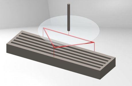
Am I visualizing the "triangle tram" idea correctly?
Triangle Tram.JPG

Circle radius for this mock-up/visualization is 6" - table is 21" x 6" (there's 3" height/z dimension between circular plane/spindle throat and top of mill table)
The triangle is 11.5" on the x-axis and 5.75" on the y-axis so the "pins" (measurement points?) were visually on the table but for ease of discussion/theory let's agree that they're coincident with the 6" radius (therefore the corners attached to the base/back edge are 12" from one another along the x-axis and 6" from the spindle center to the "front" of the triangle in the y-axis).

How I am perceiving the information presented thus far, is that if the points along the x-axis are equal, then my head is trammed(?) and if the front point is equal to those, then I don't have nod(?) (... essentially my spindle is perpendicular to the table along the x-axis and the y-axis...).

I loosely based these measurements on what I believe (the numbers in my head w/o checking) my table dimensions are (slots aren't correct) - I likely have some good 12.18" rotors on the shelf/know where to get good used (what we [racers] would consider scrap) ones that could be machined flat (they bolt to hubs so there is an open center ~7" in dia).
 
Ya, that's all pretty close. I think you did well sifting through the confusion.

Athough it isn't necessary, it really helps to zero all three indicators on the same spot. That way you can know at a glance where things are because they all read the same. But if your head can handle the translation only looking at the change, it isn't necessary. But for simplicity sake, let's assume you prefer the simple approach. That means the distance to each indicator from the spindle center has to be the same. Your 5.75" works.

It's unlikely that you can machine a used brake Rotor to be better than it is without a surface grinder. The brake pads themselves are pretty good at making a flat surface. I'd just find a good one and be done with it.

Keep in mind that this 3 pt tram device of mine is not required. In fact you don't even really need 2 points. You can do the whole thing with a single indicator measuring your bed directly. It's just that two makes it a lot easier and 3 makes it downright simple. I just thought it would be fun to make a 3 gauge unit since I've never seen or heard of anyone using one or making one.

In reality, you just need to tram your mill with a single gauge and then square your vise with the same gauge held differently, and you are good to go.
 
Back
Top