Spindle square

Susquatch

Ultra Member
Administrator
Moderator
Premium Member
I have also thought you might be able to use either of the midpoints with a half rule to get you there too but I never tried it. Then again, maybe not..... I guess I should actually try that last one before I shoot my mouth off.......LOL!

yes - doing some math and calculation is all good but in the couple minutes it takes with the spindle square.........

OK, sometimes I am a sucker for punishment and way too curious about how things work and why they work that way. I just couldn't help myself. So I did some thinking.

There are a few observations that may be obvious to many and not so obvious to others.

First off, I accept that the square tool is both fast and convenient. For those of us without one, the process isn't horrible though - just a lot more rigorous. Here are my thoughts on the matter.

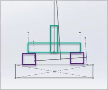
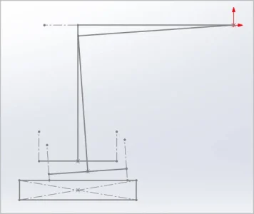
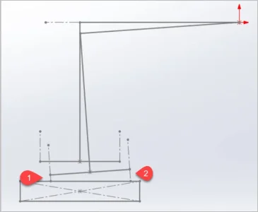
Unlike a regular clockwise / counterclockwise tram, a nod tram is not done on an axis that transects the bed. That's because the nod center of rotation is located quite a bit rear of the bed.

Therefore a standard split the difference approach to reaching tram square does not work. In fact, I was outright wrong to think it ever could.

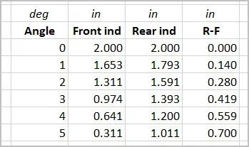
Basically, because the nod center of rotation is behind the bed, all the points that might be used on the bed to determine a tram condition all increase simultaneously as the head nods up or they all decrease simultaneously as the head nods down. However, the rate of increase or decrease changes in linear proportion to how far they are from the center of nod. The further they are forward toward the user, the faster they change.

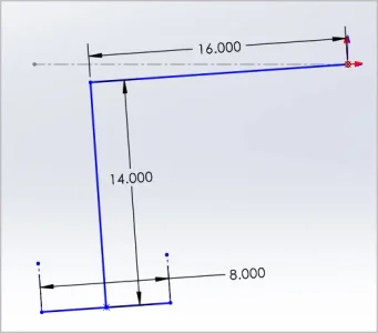
This last fact can also be used to advantage to improve tramming accuracy. I think everyone accepts that the longer the distance used to measure points on any plane, the better the obtainable accuracy. When tramming the nod, I think it is better to use the bed in the fully forward position EVEN if that means that the spindle is behind the bed. The reason for this is that moving the bed as far forward as possible, also increases the distance from the center of nod rotation to all the points that might be used and therefore increases the relative accuracy that can be achieved. For this assessment, I arbitrarily chose a point at the front of the bed and a point at the rear of the bed. As long as the head has already been trammed in the X-axis, neither one of the two nod reference points needs to be in line with the spindle. However, they do need to be somewhat consistent.

It will also be obvious to most others that adjusting nod should be done in the direction that tilts the head up. Just like moving a table or any other machining operation, backlash is best removed when working against the natural forces. In this case, gravity is trying to pull the head down, so it's best to operate the rack in the lifting direction in order to remove all the backlash while turning the nod pinion on the nod rack to change nod.

With these observations in hand, I set my mind to the business of how to tram the nod in a fast rigorous way instead of the trial and error method I have used myself and seen used elsewhere.

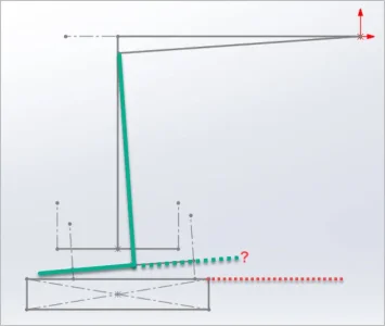
As noted above, its best to begin with the head down a bit from square. Then measure a position on the front and rear of the bed sequentially. If I began with the head nodded down a bit, the front bed position will be lower than the rear position. The head can then be lifted while measuring at the front by the entire difference between the two readings. This can be repeated until the difference is zero and then you are trammed.

The number of iterations can also be reduced by lifting the head by more than the difference. However as the difference gets small, this becomes more and more difficult to do.

If one is extremely careful, the number of iterations can be reduced to two by carefully limiting the extra adjustment to the ratio of the two point distances to the center of rotation of the nod times the difference.

However, overshooting square is easy to do, so I'm thinking that a somewhat more conservative approach is better. Besides, a few more iterations is a piece of cake if you are only swinging the indicator back and forth from the front to rear of the bed and back. Best of all, if the table is adjusted fully forward during this process, all the readings can be done without needing to go around to the other side of the mill to see the face of the indicator.

OK, so now I need to get off my butt and make a tram square......... LOL!

I might not make one that looks the same as a conventional one though. Mine will probably be triangular so I can keep the spindle behind the bed! Or does the improved accuracy really matter? Probably not for most operations. Maybe I'll make a conventional one too!
 

RobinHood

Ultra Member
Premium Member
Great description of what is happening.

Here are some thoughts:

When tramming the nod, I think it is better to use the bed in the fully forward position EVEN if that means that the spindle is behind the bed.
That takes away from the “self proving“ ability of a rod held in the spindle. You want the spindle centered over the surface you are tramming so that any bend in the rod does not affect the indicator reading because it forces the rotation of said rod in the spindle by 180* in order to measure the opposite position. I think using a triangular shaped dual indicator holder only works if you know for sure that the vertical side is exactly 90* to the horizontal side of the triangle and that the vertical extension into the spindle is proven to be straight. Making such a tool is not without challenges.

One could probably accurately tram a milling machine head without an indicator(s) by using an ordinary fly cutter holder and a rod (clamped in the tool slot), the length of which is equal to 1/2 the table width, and a piece of paper or shim stock. Start by eliminating tilt in the +/- X direction first and then adjust the nod. You are trammed when in any position on the inscribed circle it takes the same amount of force to pull the paper/shim from underneath the rod end. The accuracy is limited by the spindle bearing/straightness (a constant, no matter which method of tramming you use) and the fine feel in your fingers only. No reading parallax or hysteresis of indicator springs to worry about. It would probably take a few tries in each axis to get there.
 

PeterT

Ultra Member
Premium Member
Maybe some pictures will help. The beauty of the 2-gauge is (once calibrated square & left that way) there is only 1 job: tweak the nod angle until both dial readings read the same. Both are conveniently facing the operator from the side so relative movement & convergence will be pretty obvious. The other thing I notice, at least on my machine, is just tightening the head can influence position until its fully locked down. That's when its nice to simultaneously have your eye on the needle target to see what's going on.

I just made a fictional dimension example by eyeball to get a feel. This suggests 1 degree of nod is equivalent to 0.140" delta in gage readings. So if the dials are reading within a thou of each other, that's pretty good.

You could build a 'square' like the green sketch if I understand the idea - a vertical pin joined to a bar which is set precisely perpendicular at 90-deg. Which is probably the same or more work than the gage holder. And then what. I think it would be clumsy to implement to rest on the table or blocks or otherwise judging relative gap. The beauty of dials is they are virtually passive to the machine setup. If you need more accuracy, invest in a longer parallel & lay it along the table surface & spread the gages to suite will dramatically enhance the accuracy on same gage resolution.
 

Attachments

  • EDT-2021-11-14 10.25.11 PM.jpg
    EDT-2021-11-14 10.25.11 PM.jpg
    67.8 KB · Views: 10
  • EDT-2021-11-14 10.29.08 PM.jpg
    EDT-2021-11-14 10.29.08 PM.jpg
    15.9 KB · Views: 9
  • SNAG-2021-11-14 10.26.53 PM.jpg
    SNAG-2021-11-14 10.26.53 PM.jpg
    21.1 KB · Views: 8
  • SNAG-2021-11-14 10.50.03 PM.jpg
    SNAG-2021-11-14 10.50.03 PM.jpg
    24.3 KB · Views: 8
  • SNAG-2021-11-14 10.50.13 PM.jpg
    SNAG-2021-11-14 10.50.13 PM.jpg
    40.3 KB · Views: 9

Susquatch

Ultra Member
Administrator
Moderator
Premium Member
That takes away from the “self proving“ ability of a rod held in the spindle. You want the spindle centered over the surface you are tramming so that any bend in the rod does not affect the indicator reading because it forces the rotation of said rod in the spindle by 180* in order to measure the opposite position. I think using a triangular shaped dual indicator holder only works if you know for sure that the vertical side is exactly 90* to the horizontal side of the triangle and that the vertical extension into the spindle is proven to be straight. Making such a tool is not without challenges.

I'm not sure I understand your self proving concept. I assumed (rightly or wrongly) that setting the gauge loads the spindle the same no matter which position it is rotated to. I also assumed that a crooked or loose spindle means you are screwed no matter how much effort you put into tramming.

Maybe some pictures will help. The beauty of the 2-gauge is (once calibrated square & left that way) there is only 1 job: tweak the nod angle until both dial readings read the same.

Ya, sorry. I meant to add my drawings but forgot. Your third and fourth are like mine. Except yours are much better looking because mine are hand drawn.

Yes, after doing my assessment, I appreciate better the value of the 2 gauge tram square. But I need to understand why a triangular unit (think three gauges) wouldn't be better because it would allow the table to be further forward. Maybe after I understand @RobinHood's self proving aspect I will appreciate the situation better.

I am really loving the mill learning curve. It's a whole new world. I wish I had bought a better mill right around the same time I bought a better lathe!
 

RobinHood

Ultra Member
Premium Member
Maybe “self proving” is not the correct terminology? It is used when talking about cylinder squares and the fact that they work without error, even though they may not be 100% “square”, due to the fact that you can rotate them through 360* while they are sitting on the surface plate to eliminate the manufacturing error.

The thought I had was that unless you can rotate the measuring tool round the spindle axis, the tool itself must be know to be square to the spindle. So with your idea that the table be at the FWD most position during the nod adjustment (and thus no room to rotate the tool because the spindle axis is off the table) the tool has to have been set perfectly to the spindle axis before the measurement is made as any error will cause the nod angle to be off by the same (or larger) amount as the tool’s error to the spindle axis.

If, on the other hand, one just centers the table underneath the spindle in Y, the measuring tool can be rotated and the “self proving” concept can be taken advantage of and it absolutely does not matter that the tool’s physical axis be dead nuts inline (and it’s measuring axis 90* to that) with the spindle axis because the rotational axis will be in line and that is all that matters.

This principle can be shown with laser centering devices: as long as the laser point is rotated, the axis of the laser pointer itself does not need to be co-axial to the spindle. You just center the light circle over your desired position (center punch mark, hole, edge, etc) and the spindle center will be there as well.

Hopefully this is a more understandable description of what I was on about in the previous post.
 

Susquatch

Ultra Member
Administrator
Moderator
Premium Member
Maybe “self proving” is not the correct terminology? It is used when talking about cylinder squares and the fact that they work without error, even though they may not be 100% “square”, due to the fact that you can rotate them through 360* while they are sitting on the surface plate to eliminate the manufacturing error.

The thought I had was that unless you can rotate the measuring tool round the spindle axis, the tool itself must be know to be square to the spindle. So with your idea that the table be at the FWD most position during the nod adjustment (and thus no room to rotate the tool because the spindle axis is off the table) the tool has to have been set perfectly to the spindle axis before the measurement is made as any error will cause the nod angle to be off by the same (or larger) amount as the tool’s error to the spindle axis.

If, on the other hand, one just centers the table underneath the spindle in Y, the measuring tool can be rotated and the “self proving” concept can be taken advantage of and it absolutely does not matter that the tool’s physical axis be dead nuts inline (and it’s measuring axis 90* to that) with the spindle axis because the rotational axis will be in line and that is all that matters.

This principle can be shown with laser centering devices: as long as the laser point is rotated, the axis of the laser pointer itself does not need to be co-axial to the spindle. You just center the light circle over your desired position (center punch mark, hole, edge, etc) and the spindle center will be there as well.

Hopefully this is a more understandable description of what I was on about in the previous post.

I'm sorry @RobinHood, I still don't understand your point. Maybe I need another good nights sleep. We had 3 of our grandsons here for the weekend (7,10,&13) and they totally whacked me out.

I had thought your point involved relative movement between the indicator tip and the spindle somehow. But with your second attempt, I don't think that was your point afterall. Unfortunately, I am still left without a clear "I see".

Does your point still apply with a single indicator mounted to a swing arm that is solidly fixed to the spindle axis say using a collet on a bent indicator arm that is sweeping back and forth between front, side, and rear? If so, perhaps you could use that mechanism to explain your point because we would both have a common visual in our heads.

If not, then perhaps you could try to use that example anyway because that is the way I have always thought that it was done when one didn't own a two gauge square. So I assume that it is a valid way to do it.

Basically, I assume that a spindle axis that is perpendicular to the plane of the bed on two axis (x & y) would also be square on all other axis on the x/y plane - because that is my understanding of the definition of a plane. If that is not true then I need a refresher in my elementary math.

I also assume that a rotating spindle must be just as square as the spindle axis itself and if it isn't, then the mill badly needs a rebuild. But assuming it is, any movement of the bed in X, in Y, and in any other axis that might be obtained by a rotating spindle is square, and would be so indicated by an indicator rigidly mounted to the spindle axis no matter how long the indicator arm was or where it was used on the bed. This of course is really not quite perfect because the spring on the indicator needle does cause the indicator mounting arm to bend a bit. But if the length and geometry of the arm does not change, then that should be a constant that cancels out.

I suspect, that you think I am not using the spindle itself but perhaps the nose or the housing. That is not the case. I am using an indicator that is solidly attached to the spindle axis and that is rotated (or swept) by turning the spindle.

I am also using an indicator needle that is sweeping the bed surface. I don't have a parallel or a precision plate big enough to cover the whole bed, so some discretion must be used in choosing the best measurement location to avoid nicks and pecker marks.

I don't really see why the spindle can't be behind the bed under these conditions. A plane is a plane whether or not a solid surface is present. An indicator needle that is swept on the surface of that plane should show any non alignment between a plane that is square to the spindle axis, and the plane that is not, no matter where it is.

Sorry for being so thick.
 

RobinHood

Ultra Member
Premium Member
When tramming the nod, I think it is better to use the bed in the fully forward position EVEN if that means that the spindle is behind the bed.
My comments are based on this part of your statement.

If you do that, I can’t see how you can sweep the indicator (either a single one or the tramming tool) and still contact both the front part of the table and, after turning the indicator 180* in the spindle, contact the rear of the table. Both contact points are necessary in order for the sweep method to work and eliminate the instrument mounting error.

If you devised some sort of device so that you can have the table all the way FWD (spindle Center is now behind rear edge of the table), then the measuring device needs to be accurately calibrated beforehand and also mounted in the spindle axis to the head in order for the nod to be eliminated, because you can no longer sweep the plane of the table and thus the set-up is no longer ”self proving”.

Hope that helps.
 

DPittman

Ultra Member
Premium Member
Don't want to derail the good discussion going on but just a small update on fixing a "problem" on my spindle square that shouldn't have happened.

The stem (not the moving part) of the indicators measures .375" so when I made my holes for mounting I thought "well I'll just use a 3/8" drill bit because that will also give me some clearance as a drill bit usually drills oversize somewhat". The holes ended up being sloppy loose and I hated how the indicators bobbled around until I tightened up the screw. Ya it probably didn't matter much to the operation but it bugged me, so I bored out new holes and made brass inserts with a REAMED hole that fits perfectly now. I got to try out my new coaxial indicator for re-entering on the shaft hole. Yes too much "work/time" for the project but I enjoyed it all. My shop time makes me a better man. 20211115_143729.jpg 20211115_145534.jpg 20211115_182402.jpg
 

PeterT

Ultra Member
Premium Member
I don't really see why the spindle can't be behind the bed under these conditions. A plane is a plane whether or not a solid surface is present. An indicator needle that is swept on the surface of that plane should show any non alignment between a plane that is square to the spindle axis, and the plane that is not, no matter where it is.
Sorry, you've lost me too.
pic-1: I think a single indicator arm rotating about the spindle axis needs to make table contact on both the front & rear side of spindle is because its the difference in readings that will convey nod extent (distance 1 vs distance 2).
pic-2: A plane is a plane but if the rotated arm (dashed line on right) is off in space, then you have no physical contact reference to the measurement you made on left hand side (solid).
 

Attachments

  • EDT-2021-11-15 6.47.19 PM.jpg
    EDT-2021-11-15 6.47.19 PM.jpg
    28.7 KB · Views: 2
  • EDT-2021-11-15 6.50.10 PM.jpg
    EDT-2021-11-15 6.50.10 PM.jpg
    33.8 KB · Views: 2

Susquatch

Ultra Member
Administrator
Moderator
Premium Member
Don't want to derail the good discussion going on but just a small update on fixing a "problem" on my spindle square that shouldn't have happened.

The stem (not the moving part) of the indicators measures .375" so when I made my holes for mounting I thought "well I'll just use a 3/8" drill bit because that will also give me some clearance as a drill bit usually drills oversize somewhat". The holes ended up being sloppy loose and I hated how the indicators bobbled around until I tightened up the screw. Ya it probably didn't matter much to the operation but it bugged me, so I bored out new holes and made brass inserts with a REAMED hole that fits perfectly now. I got to try out my new coaxial indicator for re-entering on the shaft hole. Yes too much "work/time" for the project but I enjoyed it all. My shop time makes me a better man. View attachment 18316View attachment 18315View attachment 18314

She is beautiful @DPittman!

No worries, I think it was my fault that this original thread took a left turn. But it is at least on topic.

I'll be making something like yours soon enough!
 

6.5 Fan

Ultra Member
Premium Member
DPittman that looks great with those brass inserts. I will have to contemplate making one.
 

Susquatch

Ultra Member
Administrator
Moderator
Premium Member
If you do that, I can’t see how you can sweep the indicator (either a single one or the tramming tool) and still contact both the front part of the table and, after turning the indicator 180* in the spindle, contact the rear of the table. Both contact points are necessary in order for the sweep method to work and eliminate the instrument mounting error.

A plane is a plane but if the rotated arm (dashed line on right) is off in space, then you have no physical contact reference to the measurement you made on left hand side (solid).

You two guys seem to gang up on me a lot..... LOL! No worries. I'm a contrary fellow and arguments seem to follow me around! I personally love it as long as it doesn't get nasty. I usually always learn something. Debates have been a healthy part of the way humanity makes progress.

I believe I now see where we seem to fall apart. In both cases, you guys are hung up on the idea that the two indicated points need to be 180° from each other.

To repeat your concerns stated in my words, if the spindle is off the rear of table and the front indication point is at the edge, then the rear point must be off the table too and there is no place to make a measurement. And even if there were, this introduces an instrument error of some kind.

I don't see why being at 180° is necessary nor why there should be an instrument error. (Actually, I do see the instrument error, but as I'll describe later - I believe it disappears at the end.)

Assumption #1 - Imagine for a moment that we lower the table so the spindle and anything attached to it is just kinda out there hanging in space. As you turn the spindle, the tip of an instrument attached firmly to the spindle scribes a "perfect" circle that is absolutely and perfectly square to the spindle axis in all directions. I have called this assumption #1 so you can more easily focus your counterpoints if you wish.

Assumption #2 - all the points on this circle are points that are on a flat plane that extends in all directions to infinity. However, for this discussion, we can limit the plane to a flat plate - either round or square that is hanging in space above the bed. For simplicity and ease of visualization, I'd suggest that we make it a round flat plate the same size as the circle scribed by the indicator tip.

Assumption #3 - If (and only if) the bed has already been trammed in the X direction, and if (and only if the nod has NOT yet been trammed and was started low) one can visually see that the front edge of the plate is closer to the bed than the back edge. And yes, the plate does extend back behind the bed. But as both of you have pointed out, there is no place to measure the gap there.

Assumption #4 - one can measure this gap anyplace that one chooses. But, I choose to measure it at the front edge of the bed and at either rear edge of the bed were it intersects the round plate. Neither of these two points are at 180° to the front point. Nonetheless, the gap at these locations will be greater than the gap at the front. Furthermore, if the bed is truly trammed on the X-axis, both rear measurements will be the same. Lastly, a line drawn between all three points will describe a triangle with the rear leg of the triangle parallel to the rear edge of the bed.

Assumption #5 - as the nod is slowly tilted up, the DIFFERENCE between the front gap (at the front edge of the bed) and the rear gap (at the rear edge of the bed) will slowly disappear. Yes, both will get bigger, but the difference between them will shrink.

Assumption #6 - (I bet you already know what I am going to say) when the difference between the front and rear measurements gets reduced to 0.0000, the nod is trammed.

A little more discussion:

The plate does not know or care if the back edge is hanging out. The plate and the bed are either at an angle to each other with a differential gap, or they are parallel with no differential.

In the singular case of nod adjustment (as I noted 2 posts ago), there is no such thing as halves. Equidistant points have no meaning anymore. The gap at both points (no matter where they are) is either increasing or decreasing. The geometry created by a hinge point so far behind the bed dictates that. It also dictates a ratio on the rate of change - not a differential.

With respect to instrument mounting errors. I believe such errors may well exist when the plate and bed are at an angle to each other. However, I believe this error (if any) gets cancelled out when tram is reached. Because all points on the circle are in a common plane, any angular error in the instrument is absolutely the same no matter where it is. Therefore it gets cancelled out.

Please note that I am NOT claiming that either of your methods are wrong. I'm only trying to illustrate that a different method works too. In a perfect world with a huge bed, I would choose to use a 180° differential too. But we don't have that. Since the differential grows with radius distance, I would prefer to pull the bed out as far as it can go because that is where the distances are greatest.

Assuming that you both now understand what I am suggesting, I may make a triangular tram.

OK, that's it. I'm done. Hopefully you agree. My flack jacket and hard hat are on. Fire away!
 

Susquatch

Ultra Member
Administrator
Moderator
Premium Member
DPittman that looks great with those brass inserts. I will have to contemplate making one.

I dare say that @DPittman's gauge actually looks BETTER than it would have looked if the original holes had been a perfect fit! Best of all, the indicators won't get scratched!!! I love it!

Many an advance made is the result of a mistake that really wasn't......

Well done @DPittman !
 
Last edited:

Susquatch

Ultra Member
Administrator
Moderator
Premium Member
@Susquatch - is the frown you sent me now upside down? :)

Seems like you have embraced the idea of the spindle square or triangle or tetrahedron or ellipse .....etc :p

Yup, it is. As you said earlier, it isn't really "will it work?"

It's just plain easier and I'm in for that all day every day! Might make an ellipse though..... JFTFOI! How cool would that be!
 

Susquatch

Ultra Member
Administrator
Moderator
Premium Member
@Susquatch - is the frown you sent me now upside down? :)

Seems like you have embraced the idea of the spindle square or triangle or tetrahedron or ellipse .....etc :p

Imagine a deliberately twisted up gnarly looking fixture. With beautiful brass gauge mounts, And maybe a deliberate optical illusion to totally camouflage the hidden plane...... Yup, Lovin it!
 

historicalarms

Ultra Member
What is this "mill head trammeling" thing y'all are going on about....asks the guy with a big $hit eating grin & solid head mill-drill (the only time he gets to grin when comparing a Bridgeport type to a mill-drill).
 

RobinHood

Ultra Member
Premium Member
@Susquatch , no need for personal protection gear!

A agree with all your assumptions & points in post #32. It for sure will work.

Not sure if it was you or someone else said that the nod can be trammed out quickly with just a few iterations.

The main purpose of the tool that @DPittman made is to speed up the tramming process (once the tool is calibrated). I think that a tool like that can do that.

I think that’s where @PeterT and I are coming from: is the ”triangle method” advantageous to use?

If you center the spindle over the table in Y and use a point on the front edge and one 180* from it on the rear, you essentially eliminate any out of tram error of the spindle in X (tilt). (It‘s like using a cylinder square - you use two points on it 180* opposite that are at a true 90* to your reference surface, like a surface plate, or in our case the mill table). With your method, if the spindle axis is tilted even the slightest in X, the error of the plane will be magnified with your triangle method and it may be very hard to determine if you are out in the nod, the tilt or both. Is it going to work, for sure. Is it accurate - yes. Is it relatively quick - maybe not.


A little story:

I though I could tram the BP head in both X and Y at the same time when I first got the mill (a long time ago now) by just sweeping a 1/2 tenths indicator on the mill table with the mounting bolts lightly snugged up. I did understand that a plane swept by the indicator needed to be parallel to the table in order for the head to be in tram. Turns out that that is a very difficult operation and I spent a good long amount of time trying to get it. I eventually got it. I was very happy and the mill made nice square cuts.

We then decided that we are going to deck off some old railway track for an anvil (One 12” section for my son and one for me). The cutting forces were much higher than on anything we did before and the head moved. We had to tram again. Same X & Y together method was used - again, it took a long time. It was then suggested that maybe there is a better way (“why is this taking so long, dad?“). He went online to look up tramming a mill head and found that isolating tramming in X (tilt) from Y (nod) was the ticket. X is first. Been doing it like that ever since…
 

RobinHood

Ultra Member
Premium Member
Speaking of milling heads that are difficult to tram: the Huron style ones are apparently the worst because it is hard (impossible?) to isolate the X and Y directions from one another because of the oblique mounting flange. This is where a calibrated tramming tool shines.

FF6F60C1-D91B-41CE-BE4D-1B488CD1301E.jpeg
 

Susquatch

Ultra Member
Administrator
Moderator
Premium Member
Not sure if it was you or someone else said that the nod can be trammed out quickly with just a few iterations.

It was me. I was mostly having fun with Brent. Sorry if that caused a storm at sea that shouldn't be.

But I was also serious. I did both my new to me mills that way. Both were out in both axis. The halves rule handled x adroitly. The nod was also fast, probably because I instinctively interpolated the numbers after one iteration and they zeroed in very quickly. But perhaps I got lucky.

The main purpose of the tool that @DPittman made is to speed up the tramming process (once the tool is calibrated). I think that a tool like that can do that.

I agree and said so very early in our discussion. If you saw my post to @Brent H , I'll be making something VERY DIFFERENT and fun to use! I hope it will be as entertaining for all of you as I know it will be for me!

I think that’s where @PeterT and I are coming from: is the ”triangle method” advantageous to use

I believe that there are two advantages that have not been fully "flogged". One is the inherent resolution advantages of the arc at a longer radius. The other is the ability to tram both x and y simultaneously.

With your method, if the spindle axis is tilted even the slightest in X, the error of the plane will be magnified with your triangle method and it may be very hard to determine if you are out in the nod, the tilt or both. Is it going to work, for sure. Is it accurate - yes. Is it relatively quick - maybe not.

Well, given that the method outlined in our discussion only used one indicator, I'll have to concede (and did and actually already conceded that much earlier in this thread) that the two indicator system is much faster. BUT..... I believe that my soon to build and hopefully entertaining three dial system would be faster still because it can do both x and y at the same time. Of course, I never even thought about doing both like that till this orangutan character and his buddy @PeterT pushed my thinking beyond where it was stuck.

We then decided that we are going to deck off some old railway track for an anvil (One 12” section for my son and one for me).

I DID THAT TOO! About 40 years ago I lived beside a railroad track. They had a 20ft section of track they replaced and shoved the old piece into the ditch. I let it sit till it was overgrown with weeds and then decided it was safe to swipe it. I torched it into 3 short pieces and made an anvil for myself and my friend. I still use my anvil and I still have the remaining piece. It's about 3 ft long. I bet you are wondering how come I only got 2 anvils and a 3 ft piece out of a 20ft section. I'm still wondering that too. I think it probably has something to do with how mass shrinks at speeds close to the speed of light. Which is how fast my years have gone by. I swear on my wife's Fine China that it was at least 20ft long when I was dragging it home all alone..... In the dark...... Waiting for the sirens to start screaming. :eek:

My anvil still looks like a piece of short track. But I didn't have a mill till just recently. I should drag that thing out and make some improvements.......
 
Top