• Scam Alert. Members are reminded to NOT send money to buy anything. Don't buy things remote and have it shipped - go get it yourself, pay in person, and take your equipment with you. Scammers have burned people on this forum. Urgency, secrecy, excuses, selling for friend, newish members, FUD, are RED FLAGS. A video conference call is not adequate assurance. Face to face interactions are required. Please report suspicions to the forum admins. Stay Safe - anyone can get scammed.
  • Several Regions have held meetups already, but others are being planned or are evaluating the interest. The Ontario GTA West area meetup is planned for Saturday April 26th at Greasemonkeys shop in Aylmer Ontario. If you are interested and haven’t signed up yet, click here! Arbutus has also explored interest in a Fraser Valley meetup but it seems members either missed his thread or had other plans. Let him know if you are interested in a meetup later in the year by posting here! Slowpoke is trying to pull together an Ottawa area meetup later this summer. No date has been selected yet, so let him know if you are interested here! We are not aware of any other meetups being planned this year. If you are interested in doing something in your area, let everyone know and make it happen! Meetups are a great way to make new machining friends and get hands on help in your area. Don’t be shy, sign up and come, or plan your own meetup!

Tips/Techniques Show your shop related 3DP

Tips/Techniques
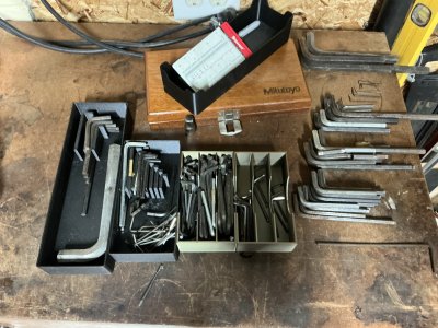
One cannot comment on the tool storage practices of others. Seems like it would be bad form :)

Nah, I love it when the guys make fun of my methods. I'm proud of my organized chaos.

I confess there are more than a few really tempting storage solutions being bounced around though.

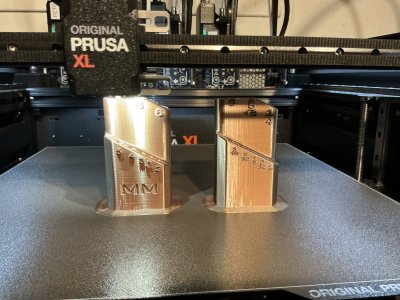
I'm quite blown away by that metallic MT3 storage rack.
 
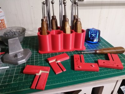
I mostly only use mine to print foundry patterns, but I did print out this fillet iron organizer when I got sick of them somehow suddenly migrating to various random parts of the house every time I'm just about to need them... Total CAD newbie here, so even with printed patterns the fillet irons do still come in handy often enough.

IMG_20241220_223445_copy_1408x1056.jpg

Jeff
 
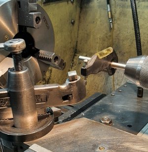
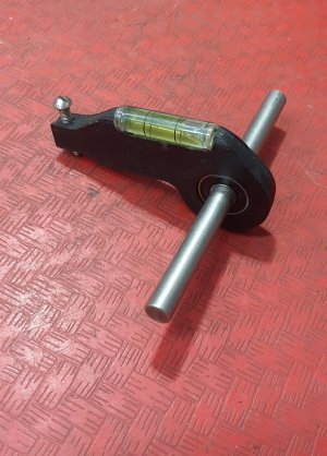
Lathe cutter height tool which can be mounted in the headstock or the tailstock. Skateboard bearing and a bubble level tube.
20250327_211611.jpg

If I put a .004'' shim on top of the cutter the bubble will be able to show the difference. The front adjusting screw make it easy to adjust and lock it in on center.
Printed 5 years ago, the design group at work got a 3D printer and it was sitting idle. Found the file on the web and asked if they could print me a couple.
20250327_211808.jpg
 
That is sooooo coooool! I'm definitely impressed!

Would a precision level bubble improve that?
For a lantern tool post setup .004" is plenty good enough. If i was to make another one, I would like it to be able to reach the tool bit in the final position. Now i set the tool height , then swivel the tool holder to align the tool cutter to the work piece and finally lock down the lantern tool post. I wish the leveling tool could measure at this point, when all is done and ready to go. So that it one of the reason I don't use it that often.
It would be easy to make a base with the level mounted to it. There is enough room on the lathe apron for a base to roam around to find and locate the cutter tip.

The reason I asked about precision is to explore the possibity of making one like that for an Aloris Style Toolpost.


I can't remember where I posted the bit about making a replacement puzzle piece but the owner of the puzzle sent me this photo. They printed the appropriate colours and glued it onto the piece.

Now it's a Find Waldo kind of thing.

1743652882827.png
 
2 o'clock from the word Diemos
You probably found the original photo I posted that showed where it was right?

"Edit: Ah Posting #90 in this thread"

Actually though you are correct. It's just a slightly different shade. Even has a tinge of white on the bottom connecting to the next piece. Very impressive. Especially since what the camera captures with ambient light and what we see may create a slightly different shade.
 
Last edited:
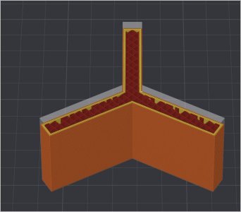
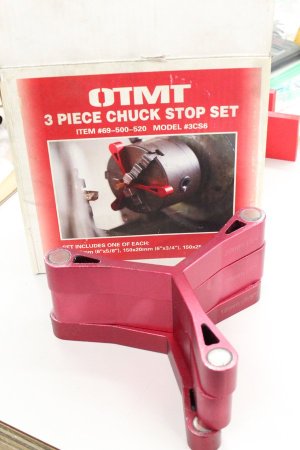
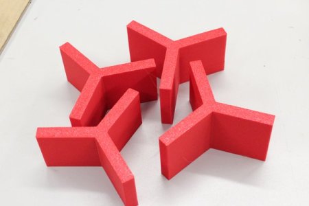
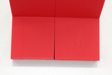
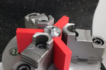
I made some 3DP chuck stops similar to the aluminum ones you see with magnets. The magnets are so they stick to the chuck & also when you stack together. I decided to omit magnets which I kind of hate around tooling anyways & just print some in progressive graduated depths. Usually you are pressing the part into the stop/chuck anyways kind of like a conventional parallel. You can see there is a crack of daylight between 2 faces. 3DP's are not perfect. I increased the layer count on the faces to give me extra sacrificial material to trim parallel & true. PLA actually machines quite nice. And if you happen to drill a hole into one, oh well, print another & eat the 50 cents or whatever.
 

Attachments

  • SNAG-26-04-2025 10.11.16 AM.jpg
    SNAG-26-04-2025 10.11.16 AM.jpg
    48 KB · Views: 11
  • 01052524.jpg
    01052524.jpg
    72 KB · Views: 10
  • 01052519.jpg
    01052519.jpg
    26.8 KB · Views: 8
  • 01052518.jpg
    01052518.jpg
    18 KB · Views: 10
  • 01052517.jpg
    01052517.jpg
    38.5 KB · Views: 10
Last edited:
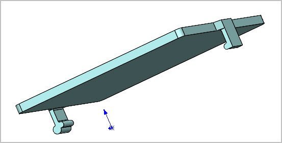
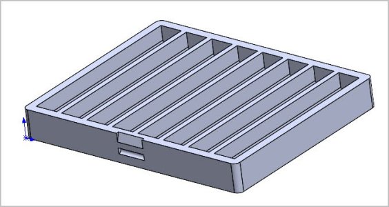
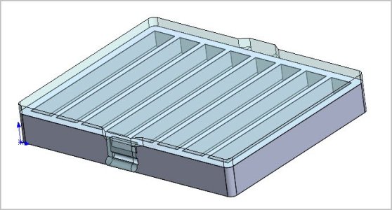
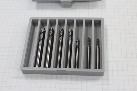
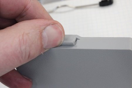
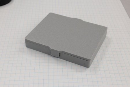
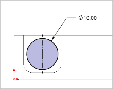
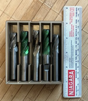
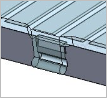
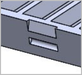
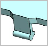
This is more of a generic tester but so far seems to work well. I wanted a lid for a typical compartment tray like holding end mills or taps or whatever. I've played around with hinges & sliding lids in a slot but they are kind of fiddly. This uses 2 integral clasps which have a positive semi-circle profile that matches a negative relief on the tray side. I made them the same width which serves double duty to prevent the lid form moving laterally. PLA is kind of rigid but I settled on this clasp overhang. The thumbnail clasp is enlarged a bit & I cut a slight ramp slot on the tray to ease engagement. It's quite secure but you can get it off with your thumbnail. Its semi-parametric. Once I come up with a tray layout the lid & clasps just update automatically.
 

Attachments

  • SNAG-03-05-2025 6.34.39 PM.jpg
    SNAG-03-05-2025 6.34.39 PM.jpg
    15.4 KB · Views: 7
  • SNAG-03-05-2025 6.34.28 PM.jpg
    SNAG-03-05-2025 6.34.28 PM.jpg
    18.9 KB · Views: 11
  • SNAG-03-05-2025 6.34.21 PM.jpg
    SNAG-03-05-2025 6.34.21 PM.jpg
    46.5 KB · Views: 7
  • SNAG-03-05-2025 6.34.13 PM.jpg
    SNAG-03-05-2025 6.34.13 PM.jpg
    48.3 KB · Views: 11
  • 03052510.jpg
    03052510.jpg
    36.1 KB · Views: 8
  • 03052509.jpg
    03052509.jpg
    24.8 KB · Views: 7
  • 03052504.jpg
    03052504.jpg
    23.9 KB · Views: 9
@pdentrem the finger groove slot is a good idea. Other trays have that feature, must be for a good reason. I was kind of focusing on the lid & clasp but there is room for improvement,

I have not done much STL manipulation. Obviously you were able to make the oblique cut for the finger groove. What app are you using?
I assume you 'scaled up' the STL to accommodate 0.5" EMs? So, I'm guessing that makes everything proportionately thicker? If so, the clasp body will grow a bit too so the latching action it might feel a bit stiffer (whereas I keep my latch the same dimensions regardless of box size). I think on that one I made the slot 12mm wide x 12mm deep (0.472") just as a nominal size for 10mm shank so it might not be a big change. And who knows, maybe PLA varies a bit & yours may feel different than mine. Anyway if it doesn't work out & you want something custom, no problem.

1746374151351.png
 
I imported into Prusaslicer 2.9.2 and added a negative part to make the finger groove and scaled to size. Yes the walls get thicker as I went 125% in X and Y. I printed the top and case at the same time. Took about 2+ hours. The latch system is a bit funky as you have to set it on the correct way.
Pierre
 

Attachments

  • IMG_9991.jpeg
    IMG_9991.jpeg
    1.6 MB · Views: 5
The latch system is a bit funky as you have to set it on the correct way.

The (slightly larger) front latch corresponds to the slot with the tapered entry ramp. To put lid on, first engage the 'rear' latch into its slot, close the lid kind of hinging on that until the front latch clicks into position (assisted entry by the ramp). The front latch is slightly enlarged for your thumbnail for removal. Like I say, yours may feel a bit different (stiffer) if the latch arm got made bigger by % enlargement.

1746380301494.png
1746380533580.png
1746380981686.png
 
I will see how it goes once I finish a second tray. I believe having both sides the same will remove the possible failure in the future. I like the design.
Pierre
 
Back
Top