I haven't seen those variable speed controls before, are they SB and what motor are you running ?
-
Scam Alert. Members are reminded to NOT send money to buy anything. Don't buy things remote and have it shipped - go get it yourself, pay in person, and take your equipment with you. Scammers have burned people on this forum. Urgency, secrecy, excuses, selling for friend, newish members, FUD, are RED FLAGS. A video conference call is not adequate assurance. Face to face interactions are required. Please report suspicions to the forum admins. Stay Safe - anyone can get scammed.
-
Several Regions have held meetups already, but others are being planned or are evaluating the interest. The Calgary Area Meetup is set for Saturday July 12th at 10am. The signup thread is here! Arbutus has also explored interest in a Fraser Valley meetup but it seems members either missed his thread or had other plans. Let him know if you are interested in a meetup later in the year by posting here! Slowpoke is trying to pull together an Ottawa area meetup later this summer. No date has been selected yet, so let him know if you are interested here! We are not aware of any other meetups being planned this year. If you are interested in doing something in your area, let everyone know and make it happen! Meetups are a great way to make new machining friends and get hands on help in your area. Don’t be shy, sign up and come, or plan your own meetup!
You are using an out of date browser. It may not display this or other websites correctly.
You should upgrade or use an alternative browser.
You should upgrade or use an alternative browser.
Tips/Techniques Show your shop related 3DP
- Thread starter PeterT
- Start date
Tips/Techniques

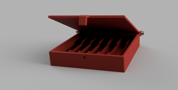
I did file the lead in ramp to get a smoother action.
Actually there really is no reason not to make a ramp on both sides, just mirror it. Then it wouldn't matter which way the lid went on. The thicker clasp on the lid is the only unique feature. I might make the thumbnail part a bit bigger. I was also thinking of something more like a circular groove on the inside corner to act like a flexure vs the sharp 90-deg corner. Details, details...


@Janger I tried this kind of hinge. I tried SHCS too a better option was mini dowel pins from Ali which are spit cheap. Just push them in the holes & a drop of CA on one end to keep it in.

Attachments
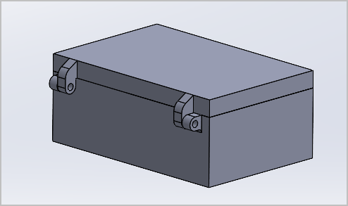
Details details... yes. I was inspired to give it a go. Trying for a hinged lid. No idea of those ears for the screws will work or just bust.


printing now in red. about an hour for the lid and 90 minutes for the box.
We need a plug in for xenforo to let you view and spin the .stl files...
That's pretty cool you can make those. For a couple tool sets I bought old empty snap on cases, hollowed out the innards and made them fit. I never would have thought of being able to make my own cases
@Janger & @PeterT
I like my stuff to fit without wasted spaces between things. Consider moving those hinges inside the box. A cone head screw could be mounted flat to the outside of the case. Put all your reinforcements inside so the only wasted space is for the hinge itself. A 3D printer should make that easy to do.
Inside hinges allow for boxes that can cuddle together without all that wasted space between them and behind them. An inside hinge also makes a propped lid (opens to say 120° or so) much easier to do.
MrWhoopee
Ultra Member
I'm running the original 1 hp, 2-speed, 3-phase motor powered and controlled by a Vevor 2.2kw VFD. I gutted the drum switch and wired it to the VFD low voltage inputs for forward and reverse. The speed control is just a 10k ohm potentiometer also wired to the VFD inputs and the tach is a $20 unit off eBay with a hall effect pickup. I printed the the tach housing and pot mount.I haven't seen those variable speed controls before, are they SB and what motor are you running ?
Nice, thanks.I'm running the original 1 hp, 2-speed, 3-phase motor powered and controlled by a Vevor 2.2kw VFD. I gutted the drum switch and wired it to the VFD low voltage inputs for forward and reverse. The speed control is just a 10k ohm potentiometer also wired to the VFD inputs and the tach is a $20 unit off eBay with a hall effect pickup. I printed the the tach housing and pot mount.
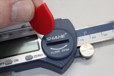
You know those instrument battery covers with the slot? Yes, the slot made to no particular standardized width, each one is a bit different. Maybe they are based on Asian coins because Canuck coins aren't much better fit than stamped metal ones assuming one was included. I just 3DP'd as set in various incremental thicknesses. Hint, don't use a blade screwdriver, they are guaranteed to mangle the soft plastic.
Attachments
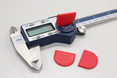
This is an example of something I've been doing more as of late. When you want to fit something with some degree of snugness but the printer tolerance and/or part tolerance can vary a bit so it becomes a trial & error repetition. Sometimes its easier to make the cavity match the actual part dimension, but add some kind of flexure slot so there is some give in the surrounding material.
Attachments


Dan Dubeau
Ultra Member
Well that's certainly a little more upscale than my screw into OSB 😀.
Still hard to believe the finish that the Bambu's create, and the speed at which they do it. Nice job!
Still hard to believe the finish that the Bambu's create, and the speed at which they do it. Nice job!
I 'saw' that too. What an amazing holder.Well that's certainly a little more upscale than my screw into OSB 😀.
Still hard to believe the finish that the Bambu's create, and the speed at which they do it. Nice job!
Dan Dubeau
Ultra Member
Ya, really cutting edge stuff! (sorry, your started it lol)
Doggggboy
Ultra Member
No need to make a big "kerf" fuffle about it.Ya, really cutting edge stuff! (sorry, your started it lol)
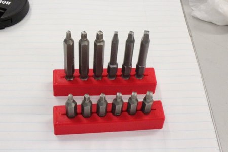
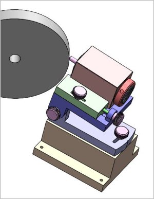
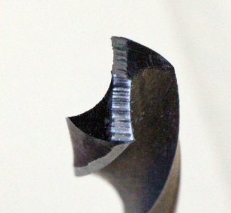
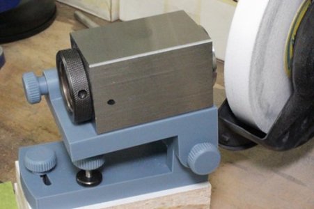
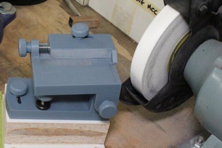
I made a similar slide plate for my TCG but its a bit of a rigmarole to set up the compound angles. I wanted to see what I could get away with with 3DP assembly & my bench grinder. The drill is held in a 5C collet block, advance into the wheel along fence up to the finger stop. Flip 180-deg & repeat. This ensure left = right. Increment infeed the fence with the mini lead screw. I was quite shocked, actually not too shabby geometry wise. Its the wrong wheel for the job & the grind striations look worse than in real life because I blackened the drill with felt marker & stroked the facet with a stone in an attempt to photo the dual angle. Yes I know, my facets don't quite meet up perfect because the whole setup is just tacked in place. The big issue I already knew from the TCG is few of these hardware store grade 'practice' drills are very coaxial or equal flute. Well, not exactly machine shop quality but it was a fun little project.
Attachments
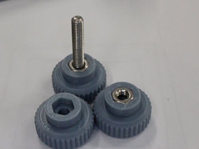
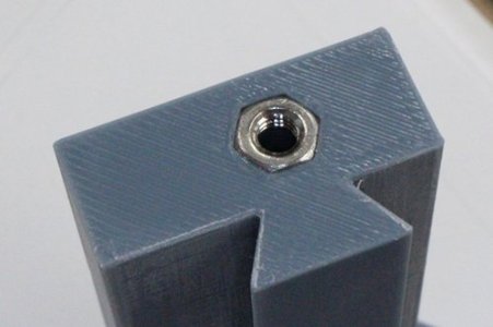
I've been comparing heat set inserts with pressed in hex nuts & I'm starting to go hex more & more. More for simplicity & nuts are just common stock vs dragging out the iron. I know some guys use those insert irons in a drill press type gadget which probably eliminate some of the variables. The nut recess is a slight interference fit. I use med/thick CA glue & they actually hold pretty well for most 3DP gadget applications. The PLA failed first when I did a removal torture test. The alignment trick in both cases is to leave the insert slightly proud of 3DP surface & then squeeze it flush to the datum surface in a vice or over a smooth block. You have to do this kind of quick with the heat inserts whereas the glue gives you some fiddle time. Excess CA can work its way up into the threads, if so just let it cure & run a tap in.