• Scam Alert. Members are reminded to NOT send money to buy anything. Don't buy things remote and have it shipped - go get it yourself, pay in person, and take your equipment with you. Scammers have burned people on this forum. Urgency, secrecy, excuses, selling for friend, newish members, FUD, are RED FLAGS. A video conference call is not adequate assurance. Face to face interactions are required. Please report suspicions to the forum admins. Stay Safe - anyone can get scammed.
  • Several Regions have held meetups already, but others are being planned or are evaluating the interest. The Ontario GTA West area meetup is planned for Saturday April 26th at Greasemonkeys shop in Aylmer Ontario. If you are interested and haven’t signed up yet, click here! Arbutus has also explored interest in a Fraser Valley meetup but it seems members either missed his thread or had other plans. Let him know if you are interested in a meetup later in the year by posting here! Slowpoke is trying to pull together an Ottawa area meetup later this summer. No date has been selected yet, so let him know if you are interested here! We are not aware of any other meetups being planned this year. If you are interested in doing something in your area, let everyone know and make it happen! Meetups are a great way to make new machining friends and get hands on help in your area. Don’t be shy, sign up and come, or plan your own meetup!

Schematics and Circuit Board layout with Fusion 360

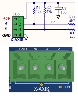
Tom was looking for clarity on scale connections to E117-00

The labels on the schematic echo those on the board.
Pin 1 = +5V (V)
Pin 2 = A
Pin 3 = B
Pin 4 = Ground (GND)

A and B can actually be swapped your DRO numbers will just go down instead of up. I would imagine there is as setting in software to reverse the direction so either method could be used.

So for your particular scales......

Scale E117-00
---------------------------
A TB6-2 A
B TB6-3 B
C TB6-1 5V
D TB6-4 Gnd


_Pinout.png
 
Also, you need to order ESP32-DevKitC core board ESP32 development board ESP32-WROOM-32D. It has to be the exact part. There are lots of these boards out there, and the pinout are different. They re available on Amazon or Ailespress. (https://vi.aliexpress.com/item/1005...st_main.5.7de11802a0ILgT&gatewayAdapt=glo2vnm).

Just a quick side question……apart from the discussion about a custom board, I’m interested in doing something, even a one off vero or strip board or whatever but I’m seeing a hurdle that I’m not equipped to jump, parts availability.

I’m seeing at Digikey/Mouser and the Aliex link that the DevKitC is NLA, can anyone point me at a direct, exact replacement?

Like I implied, I can solder acceptably but when it comes to subbing something like the DevKit it’s outside my abilities and as a wise man once said “a person has got to know their limitations”.

Thanks!

D :cool:
 
I did a R0->R1 revision of this board, that has differential inputs (better noise immunity) and uses slightly larger components. I provided the PCB files to djberta and I believe he ordered a batch.

In that R1 version I also made provision for ESP32 boards that are 0.1" wider as some varieties of the ESP boards are. The R1 board will accommodate either the narrow or wide board.
 
Which of the options? 100% compatible?

Go figure, when I saw Digikey, Mouser and the Aliex link were NLA I thought the world had moved on.

Now we just need to get Canada Post sorted out.:rolleyes:

D :cool:

They both appear from the specs to be the standard dev board, the C only denotes that it has a usb c port rather than a micro usb port

the ali links don't last long, they go nla for just about everything after a few months

is there specific non standard feature you are looking for ?
 
They both appear from the specs to be the standard dev board, the C only denotes that it has a usb c port rather than a micro usb port

the ali links don't last long, they go nla for just about everything after a few months

is there specific non standard feature you are looking for ?

I’ll have to trust you, I don’t know enough about them to get into any distinction of the features. If it’s plug and function compatible with what Yuri specified, as far as I know it should do the job.

D :cool:
 
They both appear from the specs to be the standard dev board, the C only denotes that it has a usb c port rather than a micro usb port
You gotta be careful. There are many different versions of these boards, and the pin-outs and physical size vary depending on who is making them.

The ESP 32C dev kit has a different pinout than the ESP 32U dev kit. They are NOT interchangeable. The type of USB port used is just one of the design decisions that the manufacturers make. Most are going to USB C as they come down in price. My ESP32C devkit had a micro USB port. It was still a ESP32C dev kit

You need to get the exact dev board @slow-poke calls for, or one that has the exact same pin out and physical size, or the board he designed will not function as intended.

 
You need to get the exact dev board @slow-poke calls for, or one that has the exact same pin out and physical size, or the board he designed will not function as intended.

This is exactly my holdup. I don’t know enough of the ins and outs to troll the data sheets and pick the right P/N so I have to rely on the expertise of others.

On his page, Yuri had specified a link to the correct model but as we know it’s obsolete therefore my inquiry. Sorry to be so dense about it but it’s just where my knowledge base runs out. :(

D :cool:
 
You gotta be careful. There are many different versions of these boards, and the pin-outs and p

You need to get the exact dev board @slow-poke calls for, or one that has the exact same pin out and physical size, or the board he designed will not function as intended.
To be clear I have not recommended any particular board. Tom sent me an ESP board so I could test the two boards I soldered for him, so I know for certain that board works (no idea where he sourced it), I then ordered an ESP board from Amazon that had the same pinout, however when it arrived the DIP spacing was 0.1" narrower. So when I tweaked the board R0->R1, I put another row of pads in parallel with the originals, just spaced 0.1" closer, to accommodate the narrower flavour of the ESP board.

When I went looking for ESP boards, many had different pinouts, and those obviously won't work. So if your ordering I would make sure the pin arrangement matches Tom's

In a perfect world I would have eliminated the ESP development board altogether and just put the actual ESP module, antenna and USB chip directory on the board, that would save both space and $, and would eliminate the need for the development board altogether, however I think I contributed enough at this point with so many of my personal projects on the back burner. If there is future interest I might be persuaded to do a spin without the development board.
 
Last edited:
I have some boards on order. I will update once I get them in hand.

This is the update post I've been hoping to see one of these days before disrupting my other actual and intended projects with this one....

But "E117-01 Schematic" is the one the pins need to match, yes? And there are only 15 pins that matter?
 
There are some ways around the different esp32 boards but they can get messy. I have used 24awg wire and wired pin to pin to make a board fit. It’s not pretty but does work, the hardest part really is programming the esp32 the rest is just soldering wires.
 
Back
Top