I guess that at this point I would be more after what @slow-poke is looking into. sorry for the confusion.You'll need to clarify: Are you looking for a bare board? That I have.
I THINK Jeff (@slow-poke) is going to look into getting some made and assembled by PCBWay, once they find out the cost.
-
Scam Alert. Members are reminded to NOT send money to buy anything. Don't buy things remote and have it shipped - go get it yourself, pay in person, and take your equipment with you. Scammers have burned people on this forum. Urgency, secrecy, excuses, selling for friend, newish members, FUD, are RED FLAGS. A video conference call is not adequate assurance. Face to face interactions are required. Please report suspicions to the forum admins. Stay Safe - anyone can get scammed.
-
Several Regions have held meetups already, but others are being planned or are evaluating the interest. The Calgary Area Meetup is set for Saturday July 12th at 10am. The signup thread is here! Arbutus has also explored interest in a Fraser Valley meetup but it seems members either missed his thread or had other plans. Let him know if you are interested in a meetup later in the year by posting here! Slowpoke is trying to pull together an Ottawa area meetup later this summer. No date has been selected yet, so let him know if you are interested here! We are not aware of any other meetups being planned this year. If you are interested in doing something in your area, let everyone know and make it happen! Meetups are a great way to make new machining friends and get hands on help in your area. Don’t be shy, sign up and come, or plan your own meetup!
You are using an out of date browser. It may not display this or other websites correctly.
You should upgrade or use an alternative browser.
You should upgrade or use an alternative browser.
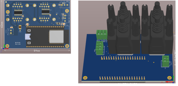
Schematics and Circuit Board layout with Fusion 360
- Thread starter Tomc938
- Start date
Hey @Tomc938. Please note that I'm on the same page as @combustable herbage. I am too old to populate a board myself. I tried to solder some 12 gauge connections the other day and my wife had to pitch in cuz I shake too much. For the most part, my main interest is in building the numbers up so this makes sense to everyone.
slow-poke
Ultra Member
Tom,....
Also, you need to order ESP32-DevKitC core board ESP32 development board ESP32-WROOM-32D. It has to be the exact part. There are lots of these boards out there, and the pinout are different. They re available on Amazon or Ailespress. (https://vi.aliexpress.com/item/1005...st_main.5.7de11802a0ILgT&gatewayAdapt=glo2vnm).
There is a bit of terminal UNIX stuff that needs to be done to install the software on the chip. I am willing to walk you through the steps. It's a bit involved.
It would be quite helpful, if you could post some instructions for the ESP32 programming procedure. Assume a Windows PC without Python installed.
mickeyf
Ultra Member
One thing to keep in mind is that the original developer promotes the idea of people building one for themselves, he even provides instructions, however not building in quantity for profit or something to that effect. Not sure how he would view having a batch of populated boards made
Thing 1:
Not a lawyer, but my reading of his license is that as long as you are not reselling or using commercially, there is no problem. A group buy of any sort (including having boards populated) for hobbyists should be fine by the letter of the license. If there is concern that it violates the spirit, that could easily be cleared up by communicating directly with him.
Thing 2:
I think @Tomc938 mentioned in some earlier post that I can't find that there are a couple of different paths being discussed here. I think these are (please clarify if I'm even more confused than usual...it IS a Monday morning)
1) Tom has a few bare boards available, there could be a group buy for components for these to be individually populated by whoever buys them from him,
2) @slow-poke is reworking the design and a group buy for components for this could be done with sufficient interest. I assume (?) this design implies a new board spin - it would be different enough that Tom's boards would not be usable even with a number of, for example, (ahem, well documented) jumpers and trace cuts,
3) Enough interest to justify Slow-poke's new board design not just being produced bare, but populated by a suitable service company, and ready to go boards delivered to the participants.
Just for the record, I'm on-board for whichever of these paths develops.
I will say that with the two small companies that I worked for that designed electronics*, the first spin of a board ALWAYS needed tweaks. Going direct to populating the boards from a brand new design does carry an element of risk, even if it's a small as "Oops! Well, a single jumper or additional pull up will fix that".
*Not my role or skill set, I just wrote software and in one case pretended to manage.
Tomc938
Ultra Member
I hear ya.Hey @Tomc938. Please note that I'm on the same page as @combustable herbage. I am too old to populate a board myself. I tried to solder some 12 gauge connections the other day and my wife had to pitch in cuz I shake too much. For the most part, my main interest is in building the numbers up so this makes sense to everyone.
I have done some surface mount projects, but with much larger components. These guys are tiny. I couldn't do it.
Tomc938
Ultra Member
Good summary!Thing 1:
Not a lawyer, but my reading of his license is that as long as you are not reselling or using commercially, there is no problem. A group buy of any sort (including having boards populated) for hobbyists should be fine by the letter of the license. If there is concern that it violates the spirit, that could easily be cleared up by communicating directly with him.
Thing 2:
I think @Tomc938 mentioned in some earlier post that I can't find that there are a couple of different paths being discussed here. I think these are (please clarify if I'm even more confused than usual...it IS a Monday morning)
1) Tom has a few bare boards available, there could be a group buy for components for these to be individually populated by whoever buys them from him,
2) @slow-poke is reworking the design and a group buy for components for this could be done with sufficient interest. I assume (?) this design implies a new board spin - it would be different enough that Tom's boards would not be usable even with a number of, for example, (ahem, well documented) jumpers and trace cuts,
3) Enough interest to justify Slow-poke's new board design not just being produced bare, but populated by a suitable service company, and ready to go boards delivered to the participants.
Just for the record, I'm on-board for whichever of these paths develops.
I will say that with the two small companies that I worked for that designed electronics*, the first spin of a board ALWAYS needed tweaks. Going direct to populating the boards from a brand new design does carry an element of risk, even if it's a small as "Oops! Well, a single jumper or additional pull up will fix that".
*Not my role or skill set, I just wrote software and in one case pretended to manage.
There is no pressure to use the boards I have. They were $3 each. Still cheaper, even if they all get trashed, for the two I ended up with than a pre-built kit.
Tomc938
Ultra Member
Remember this is Rev. 2.0. Proof of concept complete.I will say that with the two small companies that I worked for that designed electronics*, the first spin of a board ALWAYS needed tweaks. Going direct to populating the boards from a brand new design does carry an element of risk, even if it's a small as "Oops! Well, a single jumper or additional pull up will fix that".
@slow-poke nailed it the first time, and I'm sure he'll nail it again. 🙂
I find like music, sports, dancing, even pickleball it all requires practice. When I first start to solder boards with tiny parts I find my hands shake. But after a few boards it gets easier. The next day easier again.I hear ya.
I have done some surface mount projects, but with much larger components. These guys are tiny. I couldn't do it.
Now this one with 0603 parts was a bit tough. Especially the ESP32 module. Really should have been done with solder paste and an oven or hot plate instead of by hand.

Every once in a while I buy some solder paste with the intention of using it and then it ages out in the fridge. Last tube was about 8 years ago. I even bought a pneumatic dispenser to put onto the CNC router for doing that. Project #42.I found solder paste worked well. Just ran into trouble after the first few parts when I couldn’t get the paste to come out of the syringe easily/smoothly. With the arthritis in my thumbs I just couldn’t do it.
I also have two different stove top ovens that were to be modified to be the profiled soldering oven. A friend in Australia sent me his spare board and a few parts to help me finish the controller. Project #42.
And the list goes on...
slow-poke
Ultra Member
Okay a little update.....
The tested E117-00 boards ship to Tom tomorrow. No modifications required;-)
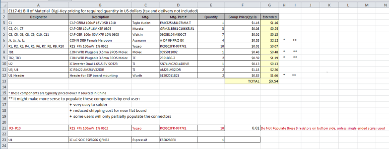
I completed the E117-01 (Improved board), see attached schematic and BOM pricing.
Assuming we build a minimum of 10 boards, component pricing is as follows (Digi-Key prices as of today):
US $9.54
Notes:
1) Add Tax, however delivery should be free (over $100CDN for group purchase)
2) It might make more sense to have the end user populate the connectors:
+ very easy to solder
+ reduced shipping cost for near flat board
+ some users will only partially populate the connectors
3) Does not include the ESP32 development board (budget $3-10 depending on source)
4) Does not include PCB cost budget about $5, this board is 1CM smaller than the original
5) Does not include population cost TBD, I find rates vary so you never really know until the quote comes in. If there is enough interest we can get quotes.
The tested E117-00 boards ship to Tom tomorrow. No modifications required;-)
I completed the E117-01 (Improved board), see attached schematic and BOM pricing.
Assuming we build a minimum of 10 boards, component pricing is as follows (Digi-Key prices as of today):
US $9.54
Notes:
1) Add Tax, however delivery should be free (over $100CDN for group purchase)
2) It might make more sense to have the end user populate the connectors:
+ very easy to solder
+ reduced shipping cost for near flat board
+ some users will only partially populate the connectors
3) Does not include the ESP32 development board (budget $3-10 depending on source)
4) Does not include PCB cost budget about $5, this board is 1CM smaller than the original
5) Does not include population cost TBD, I find rates vary so you never really know until the quote comes in. If there is enough interest we can get quotes.
Attachments
slow-poke
Ultra Member
2) @slow-poke is reworking the design and a group buy for components for this could be done with sufficient interest. I assume (?) this design implies a new board spin - it would be different enough that Tom's boards would not be usable even with a number of, for example, (ahem, well documented) jumpers and trace cuts,
I will say that with the two small companies that I worked for that designed electronics*, the first spin of a board ALWAYS needed tweaks. Going direct to populating the boards from a brand new design does carry an element of risk, even if it's a small as "Oops! Well, a single jumper or additional pull up will fix that".
Agreed any board spin has some risk, that being said I'm batting about 95% on the last 100 designs. This is a really simple board (almost brain dead simple, okay I just tempted Murphy) ;-)
Someone offered to include this PCB in their next PCB order and that makes a lot of sense to me, will reduce the risk to zero, and this board is very easy to hand populate.
Last edited:
I find like music, sports, dancing, even pickleball it all requires practice.
Obviously you don't have advanced old age tremer. Practice and muscle memory only makes it worse. Had a nice quiet relaxed lunch with a buddy yesterday. When it was time to leave, he grabbed me with both hands, looked me in the eye and recommended I get tested for Parkinson's. I told him I have already been evaluated by a neurologist. It's just old age tremers. It isn't going away, medicine doesn't help, and it isn't gunna get better - only worse.
As someone who makes A LOT of smd boards, may I offer two suggestions which will make this a whole lot easier for those doing this for the first time...
1) buy a stencil. That makes the solder paste placement extremely easy, and accurate. The board manufacturer will supply those for a small charge. Stencil costs are around $10, a stainless steel stencil will last for a couple of hundred boards.
2) those microscopic 0603 or 0805 parts - buy BIGGER ones! If the board is designed with 0603 parts, there is no reason why you cannot use larger ones - say 0805 instead of 0603 or 1206 instead of 0805. In the future, unless the board actually needs tiny parts due to layout, design with 1206 parts instead. It really makes things much easier!
And for those serious about this, l would suggest you take a look at how to use a toaster oven to do the soldering for you, it is so much easier for those of us with poor eyesight and shaky hands.
Stencil, board and part trays:

Solder paste applied and parts placed

Positioned, before heating

PID reflow controller for the toaster oven. This follows the correct solder profile

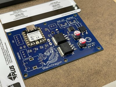
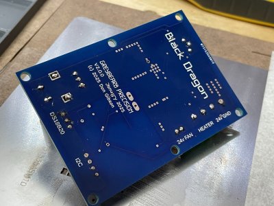
Out of the oven. All SMD parts are soldered in one pass

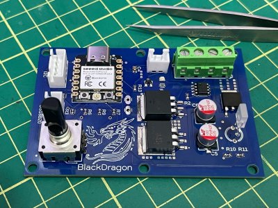
Assembled board


The board was designed in F360, and the 3D board was then used to design the case.

Testing - this is a thermal image showing the board and a warm regulator under power.

Total time from parts to tested board was 90 minutes.
1) buy a stencil. That makes the solder paste placement extremely easy, and accurate. The board manufacturer will supply those for a small charge. Stencil costs are around $10, a stainless steel stencil will last for a couple of hundred boards.
2) those microscopic 0603 or 0805 parts - buy BIGGER ones! If the board is designed with 0603 parts, there is no reason why you cannot use larger ones - say 0805 instead of 0603 or 1206 instead of 0805. In the future, unless the board actually needs tiny parts due to layout, design with 1206 parts instead. It really makes things much easier!
And for those serious about this, l would suggest you take a look at how to use a toaster oven to do the soldering for you, it is so much easier for those of us with poor eyesight and shaky hands.
Stencil, board and part trays:
Solder paste applied and parts placed
Positioned, before heating
PID reflow controller for the toaster oven. This follows the correct solder profile
Out of the oven. All SMD parts are soldered in one pass
Assembled board
The board was designed in F360, and the 3D board was then used to design the case.
Testing - this is a thermal image showing the board and a warm regulator under power.
Total time from parts to tested board was 90 minutes.
Attachments
Last edited:
Nicely done. Which toaster oven controller are you using?As someone who makes A LOT of smd boards, may I offer two suggestions which will make this a whole lot easier for those doing this for the first time...
1) buy a stencil. That makes the solder paste placement extremely easy, and accurate. The board manufacturer will supply those for a small charge. Stencil costs are around $10, a stainless steel stencil will last for a couple of hundred boards.
2) those microscopic 0603 or 0805 parts - buy BIGGER ones! If the board is designed with 0603 parts, there is no reason why you cannot use larger ones - say 0805 instead of 0603 or 1206 instead of 0805. In the future, unless the board actually needs tiny parts due to layout, design with 1206 parts instead. It really makes things much easier!
And for those serious about this, l would suggest you take a look at how to use a toaster oven to do the soldering for you, it is so much easier for those of us with poor eyesight and shaky hands.
Stencil, board and part trays:
View attachment 61252
Solder paste applied and parts placed
View attachment 61253
Positioned, before heating
View attachment 61251
PID reflow controller for the toaster oven. This follows the correct solder profile
View attachment 61249
Out of the oven. All SMD parts are soldered in one pass
View attachment 61248
Assembled board
View attachment 61247
View attachment 61255
The board was designed in F360, and the 3D board was then used to design the case.
View attachment 61256
Testing - this is a thermal image showing the board and a warm regulator under power.
View attachment 61246
Total time from parts to tested board was 90 minutes.
My PIC18F877 controller died. It used a WinDoze UI which refuses to run on Win10 or 11, and anyway I no longer have a Microchip programmer to fix things.... so it is joining more old windows stuff heading to the junk bin soon. The Teensy and the new Espressiv chips are light years ahead of the PIC technology.Nicely done. Which toaster oven controller are you using?
This is a Reflow-Pro which I bought from UnexpectedMaker in Australia. It arrives fully assembled, - just add power hardware, SSR, cables, plugs, etc. He offers a nice 3DP case for it too. About 140 beans, delivered. It also uses an ESP32 and is MQTT, WiFi, BLE capable. There's a nice web interface for managing the solder profiles too.
🙂
Last edited:
I can not type when Im in a hurry. If you guys do the bulk buy, I do not need my two boards assembled, I can do that myself.
Last edited:
Out of stock everywhere except one and they don't ship to Canada. It's on the list of 42 projects. For now I'm still doing fine hand soldering the few boards that I make. Good to know about this one though.My PIC18F877 controller died. It used a WinDoze UI which refuses to run on Win10 or 11, and anyway I no longer have a Microchip programmer to fix things.... so it is joining more old windows stuff heading to the junk bin soon. The Teensy and the new Espressiv chips are light years ahead of the PIC technology.
This is a Reflow-Pro which I bought as a kit from UnexpectedMaker in Australia. It arrives fully assembled, - just add power hardware, SSR, cables, plugs, etc. He offers a nice 3DP case for it too. About 140 beans, delivered. It also uses an ESP32 and is MQTT, WiFi, BLE capable. There's a nice web interface for managing the solder profiles too.
🙂
Thanks
Tomc938
Ultra Member
Sent you a PMGuys I can take the parts and boards and do the soldering myself. I have no problem assembling the boards on my own. The 2 boards that I would like by the way. I like the idea of making.
I can not type when Im in a hurry. If you guys do the bulk buy, I do not need my two boards assembled, I can do that myself.