The BEST suppliers listen and solve problems that allow you to work on better and innovative designs.From 40+ years of selling industrial equipment. The difference between a poor supplier and a good supplier isn’t price, quality of the goods, or delivery. The differentiating factor is what happens when something goes wrong. Good suppliers fix the error without arguing.
-
Scam Alert. Members are reminded to NOT send money to buy anything. Don't buy things remote and have it shipped - go get it yourself, pay in person, and take your equipment with you. Scammers have burned people on this forum. Urgency, secrecy, excuses, selling for friend, newish members, FUD, are RED FLAGS. A video conference call is not adequate assurance. Face to face interactions are required. Please report suspicions to the forum admins. Stay Safe - anyone can get scammed.
-
Several Regions have held meetups already, but others are being planned or are evaluating the interest. The Calgary Area Meetup is set for Saturday July 12th at 10am. The signup thread is here! Arbutus has also explored interest in a Fraser Valley meetup but it seems members either missed his thread or had other plans. Let him know if you are interested in a meetup later in the year by posting here! Slowpoke is trying to pull together an Ottawa area meetup later this summer. No date has been selected yet, so let him know if you are interested here! We are not aware of any other meetups being planned this year. If you are interested in doing something in your area, let everyone know and make it happen! Meetups are a great way to make new machining friends and get hands on help in your area. Don’t be shy, sign up and come, or plan your own meetup!
You are using an out of date browser. It may not display this or other websites correctly.
You should upgrade or use an alternative browser.
You should upgrade or use an alternative browser.
Robot Arm
- Thread starter jcdammeyer
- Start date
Well DIMAR has my vote. For a $7 part to ship a replacement Purolator is pretty good support.From 40+ years of selling industrial equipment. The difference between a poor supplier and a good supplier isn’t price, quality of the goods, or delivery. The differentiating factor is what happens when something goes wrong. Good suppliers fix the error without arguing.
King Canada sent me a set of drive gears for my KC-15VS.
(Free - under warranty)
Canada Post got them from Montreal to Kitchener in 3 days.
I think I will have to test the Canada Post route again for small items.
If there is any weight to the package . . . I think the result would be different.
(Free - under warranty)
Canada Post got them from Montreal to Kitchener in 3 days.
I think I will have to test the Canada Post route again for small items.
If there is any weight to the package . . . I think the result would be different.
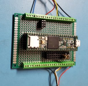
While sitting around not wanting our sick dog to be alone I decided to take a closer look at the robot arm software and since the 4 conductor shielded cable arrived from AliExpress I decided to mount an encoder onto the back of the J4 motor and wire the motor up to the stepper driver and it plus encoder up to the Teensy 3.5.
Rather than use the stupid proto-jumpers I put it onto a circuit board and mounted screw terminals. Then jumpers on the back to connect the socket for the Teensy to the terminal strip.
The other thing is the encoders are 5V devices as is the Teensy 3.5 with respect to being able handle 5V signals. However if I want to move up to the more advanced AR4 system with the Teensy 4.1 I can't subject it to 5V signals according to the data sheet.
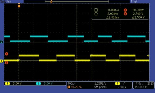
So installed some more socket strips and set it up so I can either plug in jumper wires or resistor networks that drop the 5V down to about 2.7V to 2.9V and that creates a nice lower voltage quadrature signal. I can home the Joint 4 motor by actuating the switch as it turns in the direction of the calibration switch.
Now I really want to get some of the mechanicals built.
Rather than use the stupid proto-jumpers I put it onto a circuit board and mounted screw terminals. Then jumpers on the back to connect the socket for the Teensy to the terminal strip.
The other thing is the encoders are 5V devices as is the Teensy 3.5 with respect to being able handle 5V signals. However if I want to move up to the more advanced AR4 system with the Teensy 4.1 I can't subject it to 5V signals according to the data sheet.
So installed some more socket strips and set it up so I can either plug in jumper wires or resistor networks that drop the 5V down to about 2.7V to 2.9V and that creates a nice lower voltage quadrature signal. I can home the Joint 4 motor by actuating the switch as it turns in the direction of the calibration switch.
Now I really want to get some of the mechanicals built.
Attachments
I'm on a similar trajectory with a Teensy 4.1 and a custom controller board running grblHAL - the 32 bit version of GRBL driving my 5 DOF gear hobbing machine (more later).While sitting around not wanting our sick dog to be alone I decided to take a closer look at the robot arm software and since the 4 conductor shielded cable arrived from AliExpress I decided to mount an encoder onto the back of the J4 motor and wire the motor up to the stepper driver and it plus encoder up to the Teensy 3.5.
Rather than use the stupid proto-jumpers I put it onto a circuit board and mounted screw terminals. Then jumpers on the back to connect the socket for the Teensy to the terminal strip.
The other thing is the encoders are 5V devices as is the Teensy 3.5 with respect to being able handle 5V signals. However if I want to move up to the more advanced AR4 system with the Teensy 4.1 I can't subject it to 5V signals according to the data sheet.
So installed some more socket strips and set it up so I can either plug in jumper wires or resistor networks that drop the 5V down to about 2.7V to 2.9V and that creates a nice lower voltage quadrature signal. I can home the Joint 4 motor by actuating the switch as it turns in the direction of the calibration switch.
Now I really want to get some of the mechanicals built.
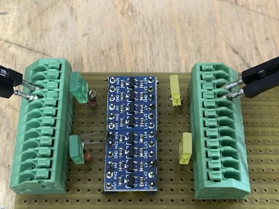
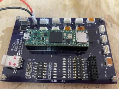
With the T4.1, level shifters are required for most peripherals (LCD, OLEDS, some I2C devices, etc) I purchased the shifters from Amazoom for about $1 each and mounted them on a veroboard with spring terminals which is a great option when breadboarding.
I made my controller some time ago, with 4 pin GH1.25 connectors for a very neat wiring setup. This board exposes most of the ports and allows up to 4 steppers. I also purchased a T4.1 carrier from Phill Barrett (via Tindie.com) which uses screw terminals for connections. Here are pics of both boards:
🙂
Attachments
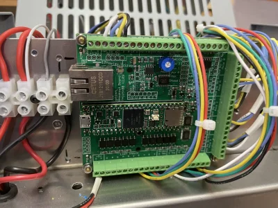
Nicely done!!!I'm on a similar trajectory with a Teensy 4.1 and a custom controller board running grblHAL - the 32 bit version of GRBL driving my 5 DOF gear hobbing machine (more later).
With the T4.1, level shifters are required for most peripherals (LCD, OLEDS, some I2C devices, etc) I purchased the shifters from Amazoom for about $1 each and mounted them on a veroboard with spring terminals which is a great option when breadboarding.
I made my controller some time ago, with 4 pin GH1.25 connectors for a very neat wiring setup. This board exposes most of the ports and allows up to 4 steppers. I also purchased a T4.1 carrier from Phill Barrett (via Tindie.com) which uses screw terminals for connections. Here are pics of both boards:
🙂
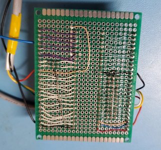
The Stepper Online drivers work with 3.3V tied to the DIR+ or OPTO pins. That means the Teensy doesn't have to be exposed to 5V and there's enough current to still drive the steppers therefore no external drivers required here.

The limit switches on the original AR3 were single pole double throw with +5 on one contact and ground on the other to combat noise it was said. Instead I used 330R resistors to 3.3V and only ran ground and signal to the Teensy. I don't expect to have noise issues with 10mA flowing through the switch when made. I used 0805 size resistors that are barely visible on the bottom of the board by the violet wires.

Saves first wiring it to 5V and then to 3.3V when switching to Teensy 4.1.
That was very easy. Remove Teensy 3.5 and insert Teensy 4.1. Run Arduino software to program AR4_teensy41_CUI_sketch_v3.0.ino into it. The major difference is this version knows I'm using the external CUI encoders as opposed to the StepperOnLine Internal encoders. They have a different number of lines per rev so the difference is in a set of 6 constants; one for each axis.
Ran the AR4 Rev 3 software on the PC. No problems and only 3V signals into it. Time to make the other 10 resistor dividers.

Ran the AR4 Rev 3 software on the PC. No problems and only 3V signals into it. Time to make the other 10 resistor dividers.
Machining question here for the robot arm. Here's a 3D print of the object.

Pressed in with a friction fit into either end of the hub are needle roller bearings.

The bearings are pressed in against shoulder in the middle of the part and should line up perfectly. Now I could bore it out at a press fit diameter of 1.25" and then just insert a spacer between the two.
Alternatively, as we've been talking about a rotary table perhaps bore one end, turn it 180 degrees and then bore the other end. Assuming the rotary table is properly fitted against mill table the holes will then be concentric, parallel with each other and the mounting base.
Any other solutions seem like... well ... difficult.
Pressed in with a friction fit into either end of the hub are needle roller bearings.
The bearings are pressed in against shoulder in the middle of the part and should line up perfectly. Now I could bore it out at a press fit diameter of 1.25" and then just insert a spacer between the two.
Alternatively, as we've been talking about a rotary table perhaps bore one end, turn it 180 degrees and then bore the other end. Assuming the rotary table is properly fitted against mill table the holes will then be concentric, parallel with each other and the mounting base.
Any other solutions seem like... well ... difficult.
Attachments
I don't think this approach is practical.

For one thing the probe can't reach the edge closest to the face so I'd have to create a jig that moves it out but also properly centres it around both axis. The rotary table axis here is the elbow joint. Turning in the hole is the forearm+wrist. If it's not aligned then putting the end effector at a point XYZ will be different depending on the angle of the elbow.
So now I'm thinking first bore the smaller hole down the middle so it's on axis with the elbow pivot. Then clamp it in the vice and probe it to find the center and bore 1.25" diameter for 1". Flip it over, find the center of the hole again and bore the second at 1.25" for 1" depth.
Comments?
140mower
Don
Bolt it to the saddle of your lathe and line bore it from both ends in the one setup.....I don't think this approach is practical.
View attachment 38917
For one thing the probe can't reach the edge closest to the face so I'd have to create a jig that moves it out but also properly centres it around both axis. The rotary table axis here is the elbow joint. Turning in the hole is the forearm+wrist. If it's not aligned then putting the end effector at a point XYZ will be different depending on the angle of the elbow.
So now I'm thinking first bore the smaller hole down the middle so it's on axis with the elbow pivot. Then clamp it in the vice and probe it to find the center and bore 1.25" diameter for 1". Flip it over, find the center of the hole again and bore the second at 1.25" for 1" depth.
Comments?
My heavily inflated two cents worth......
Comments?
No CNC expertise here. Just following along and enjoying the journey.
Why does the probe need to find the inside edge of the bore? Doesn't finding the outside edge and the front and back accomplish the same goal? For that matter, doesn't it remember where the center is from when it did the hole?
That was the approach (from one end) to bore the spindle hole for the Gingery Lathe.Bolt it to the saddle of your lathe and line bore it from both ends in the one setup.....
My heavily inflated two cents worth......
I went into the box of parts I've ordered for the AR4 Robot arm to see if the needle bearings would fit the 3D print. Turns out I forgot to order those two bearings. A bit of research showed Amazon at 2 for $24 (Prime shipping) or AliExpress at 2 for $20 including shipping. So what to do? Wait a month to save $4 or get 2 day delivery from Amazon.
So two days later here they are.

And no they don't fit into the 3D print so here's a good opportunity to try boring out the plastic and if I screw it up just print another one. First stab at it will be with the boring bar and the part held in the vise with the center line found with my probe.
At the moment setting up a boring bar on the lathe to be able to go in from both ends and have everything aligned is way more work.
Edit: Oh and they are 1.25" OD, 1" ID and 1" long.
So two days later here they are.
And no they don't fit into the 3D print so here's a good opportunity to try boring out the plastic and if I screw it up just print another one. First stab at it will be with the boring bar and the part held in the vise with the center line found with my probe.
At the moment setting up a boring bar on the lathe to be able to go in from both ends and have everything aligned is way more work.
Edit: Oh and they are 1.25" OD, 1" ID and 1" long.
So what to do? Wait a month to save $4 or get 2 day delivery from Amazon.
So two days later here they are.
That would have been my choice too. Not just because the price difference was low but also because amazon returns are also easy peasy.
Not sure I understand that.Why not machine a shaft to slide into it that will give you the access for the probe?
Good point. I think the rotary table approach is incorrect.No CNC expertise here. Just following along and enjoying the journey.
Why does the probe need to find the inside edge of the bore? Doesn't finding the outside edge and the front and back accomplish the same goal? For that matter, doesn't it remember where the center is from when it did the hole?
Instead first mill the outside faces. Then sit vertically in the vise and locate where the centre is supposed to be from those outer edges. It's not the centre of the four edges. It's offset. But as long as I can reference two of the same edges to find the hole centre I can then drill/bore the first hole all the way through to the inner ring size. Then bore down 1" for the 1.25" diameter. Flip it around and reference that first hole and enlarge it to 1.25" for 1" deep.
If the original hole all the way through is parallel to the flange face the enlarged holes will be too.
Edit: Spelling mistake. how to hole
Last edited:
Alright. This is where I love CNC. After figuring out with the MPG a decent feed rate at 800 RPM I set the Z0 to the top surface and fed down at 2" minute. Then ran multiple passes until I measured just over 1.25" the same diameter as the bearings.
Then flipped it over, used the probe to find the new X position leaving the Y the same since the based was against the vise jaw. Reset the top to Z=0 and ran a pass and then a second cleanup pass with the same dimension.
Cleaned up the 3D printed holes nicely. The bearings are a light friction fit rather than press since I want to be able to pull them out.

Unfortunately I don't have a single piece of 1" OD tube or rod in stock. I'd have to cut something down or just go and buy some stock so I can't test how well the two bearings are lined up but I'm going to assume if the two ends that rested on the vise base were perpendicular to the existing hole then it won't be tilted and the holes should line up.

Once I stick a tube through I'll set it on the surface plate and see if the tube is parallel to the base. Should be but I'm not a fan of 'should'
Then flipped it over, used the probe to find the new X position leaving the Y the same since the based was against the vise jaw. Reset the top to Z=0 and ran a pass and then a second cleanup pass with the same dimension.
Cleaned up the 3D printed holes nicely. The bearings are a light friction fit rather than press since I want to be able to pull them out.
Unfortunately I don't have a single piece of 1" OD tube or rod in stock. I'd have to cut something down or just go and buy some stock so I can't test how well the two bearings are lined up but I'm going to assume if the two ends that rested on the vise base were perpendicular to the existing hole then it won't be tilted and the holes should line up.
Once I stick a tube through I'll set it on the surface plate and see if the tube is parallel to the base. Should be but I'm not a fan of 'should'
On the way back into the house I looked at my pile of raw material for casting and noticed some aluminum tube garden chair parts. Brought in the straightest piece and cut a 12" or so section from it since it was just over 1" by a few thou.
Chucked the cut piece into the 5C collet and sanded up until 400 grit. Fairly smooth except for the slightly flat area where it was probably scraped against the ground. Anyway... It fits. But it's tight. It turns and would work for the total travel distance of 329 degrees. It's turned by a small stepper motor with a 14:1 reduction drive connected to a 2.8:1 toothed belt.

Turns out of course that before boring the two holes I should have made sure that the two reference surfaces were flat and parallel. The 3D printed surfaces were not. My bad. That's why the bearings don't quite line up.

There's enough flex to push it in. But this is why it's nice to practice. Learned something from this exercise.

Chucked the cut piece into the 5C collet and sanded up until 400 grit. Fairly smooth except for the slightly flat area where it was probably scraped against the ground. Anyway... It fits. But it's tight. It turns and would work for the total travel distance of 329 degrees. It's turned by a small stepper motor with a 14:1 reduction drive connected to a 2.8:1 toothed belt.
Turns out of course that before boring the two holes I should have made sure that the two reference surfaces were flat and parallel. The 3D printed surfaces were not. My bad. That's why the bearings don't quite line up.
There's enough flex to push it in. But this is why it's nice to practice. Learned something from this exercise.
The large compression fittings arrived today. I had to order these since all the other inventory I had was for smaller ones. These ended up costing $1.11 each for 10 of the white ones and 10 Black ones.
Of course then I discovered that the holes in my modified box were the wrong size. No problem when one has a 3D printer. Design and print an adapter ring.

Of course then I discovered that the holes in my modified box were the wrong size. No problem when one has a 3D printer. Design and print an adapter ring.