Playing around with Fusion 360

StevSmar

(Steven)
Premium Member
I'm finding it easier to set up joints and motion but it sometimes requires some thought to make the motion work correctly.
That was my experience too.

I eventually wanted “custom” joints and started using joking origins- but had to be careful to put them inside a component so they could be switched off after I had used them in the assembly (maybe this annoyance has been fixed now?)(For a component that had a joint origin, I’d make a sub-component to put the joint origins in, I’d then have to use an as-built joint between the parent component and the child component that contained the joint origins. It seems a bit “hokey” to me.
I am now starting to see why a space mouse would be useful. I now spend a lot of time moving the model around to select points during assembly.
Yes, being able to quickly rotate 180 degrees and zoom in on the mating face made it easier, though sometimes the default behaviour of turning the first component that was being jointed opaque, worked fine.
 

gerritv

Gerrit
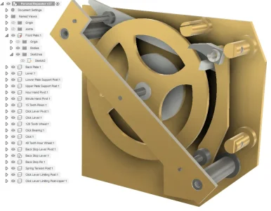
Dial mechanism for a Synchronome Clock. Ready to make dwgs for machining. the holes in Front Plate will get spot drilled on the CNC. All components sketched in place in 1 assembly. Free version of Fusion360.

1698342669805.png
 

StevSmar

(Steven)
Premium Member
All components sketched in place in 1 assembly.
That’s a sensible way of structuring your drawings. I think the primary reason to have separate files are:
- if components can be used in more than one model.
- if the size of the model starts crashing your computer.
- as a way of organizing things. (Like if you work on a small part, didn’t finish it but want to come back to it eventually. Then you can update that component and if you’re very lucky when it updates in your main assembly you don’t get any lost reference warnings…)
 

StevSmar

(Steven)
Premium Member
They also seem to have “Christmas/Boxing Day” specials.

So far, there hasn’t been any functionality I’ve needed to need the paid version. But that could just be the type of modelling I’m doing?
 

gerritv

Gerrit
That’s a sensible way of structuring your drawings. I think the primary reason to have separate files are:
- if components can be used in more than one model.
- if the size of the model starts crashing your computer.
- as a way of organizing things. (Like if you work on a small part, didn’t finish it but want to come back to it eventually. Then you can update that component and if you’re very lucky when it updates in your main assembly you don’t get any lost reference warnings…)
I actually started this model with the Front Plate as everything mounts to that. then using my fav method of doing Powerpoint, I created empty componets for everything needed for the assembly (at least those I want to model). I then worked on a component, using S/Project to get the hole locations and modeled from there. Moving locations this shifted everything else due to In Place joints.

I seldom re-use parts but I do see how splitting those out would be a wise thing
 

gerritv

Gerrit
They also seem to have “Christmas/Boxing Day” specials.

So far, there hasn’t been any functionality I’ve needed to need the paid version. But that could just be the type of modelling I’m doing?
My theory is to buy a month subscription if I ever need the added functionality, But has never come up in 4+ years :)
 

StevSmar

(Steven)
Premium Member
buy a month subscription if I ever need the added functionality
That a sensible idea.

I contemplated getting a full subscription when I was heavily modelling, since I felt bad I was having so much fun for free… Now I need a better laptop to make much more progress…
 

Upnorth

Well-Known Member
That’s a sensible way of structuring your drawings. I think the primary reason to have separate files are:
- if components can be used in more than one model.
- if the size of the model starts crashing your computer.
- as a way of organizing things. (Like if you work on a small part, didn’t finish it but want to come back to it eventually. Then you can update that component and if you’re very lucky when it updates in your main assembly you don’t get any lost reference warnings…)
I tried this method when I first watched a video of assemblies with fusion 360. The logic of it for me fell apart when I did my first radial pattern. The tree on the left immediately got enormous and lots of parts still had to be added.

Now I make a folder then individually model the components each in their own section. Then I drag them into one assembly and align them as required.
 

gerritv

Gerrit
You can manage the growth of the tree by using sub components in there as well. So e.g Cylinder Head, and then within that component you create components for Valve Guide, Valve Spring, Exhaust Valve etc. This lets you Copy (the sub assembly) and Paste New to replicate the entire sub assembly.
 

Upnorth

Well-Known Member
You can manage the growth of the tree by using sub components in there as well. So e.g Cylinder Head, and then within that component you create components for Valve Guide, Valve Spring, Exhaust Valve etc. This lets you Copy (the sub assembly) and Paste New to replicate the entire sub assembly.
Yeah that is sort of what I have been looking into. In post 1 on here a good example of where that will work is with the bushings. They will never move or need to be modified.
 

Johnwa

Ultra Member
Now, I’m on year 2 of Solidworks Maker with no regrets.
My quick read of the SWmaker restrictions is that any files created could only be opened in SWmaker and would not work with regular SW. I didn’t see whether SWmaker would opened an SW file or not. Have you tried opening an SW file?
 

PeterT

Ultra Member
Premium Member
@Johnwa you should repost this question into the SW Maker thread recently started so people can get a perspective of that app. I'd be happy to try an experiment with @BaitMaster to determine the answer.


Upnorth

Well-Known Member
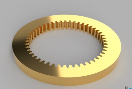
One of the really nice things about Fusion 360 is modeling gears. Time to model this gear was less than 1 minute. There is an add on module that makes it easy. It's called FM gears. An engine I'm interested in requires 2 of these. $250 USD each last time I checked. These might be a good candidate to use the CNC mill to make. Even if it's slow it would be well worth it.

Gear.jpg
 

PeterT

Ultra Member
Premium Member
I looked into this in quite a bit of detail when I (eventually purchased) an internal ring gear for my model radial engine. When you get into the math, there are a lot of factors that go into tooth design as a function of module & pitch - varying clearances, compensations, fillets & radii. These factors are somewhat unique to internal gears. The bottom line is some of these CAD profile generators vary in how much detail they go into it (ranging from borderline bogus to pretty good). This may not matter depending on your application, but something to inquire about because IMO for typical mechanical devices you might be in the range where it does matter.

BTW if you are looking at metric gears, this is a good supplier. USA distributer of German components. You might find, depending on size, they aren't nearly as expensive vs N-Am suppliers.
 

StevSmar

(Steven)
Premium Member
One of the really nice things about Fusion 360 is modeling gears.
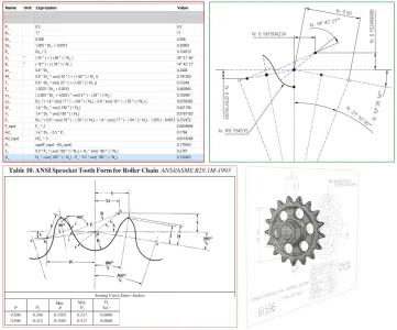
Or you can model the gears yourself using the formulas in a textbook for gear profiles. But this approach is really only feasible if the number of gear teeth required does not vary.

This is the sprocket I modelled, including the formulas (the formula’s came from Machineries Handbook):
IMG_7762.png
 

Upnorth

Well-Known Member
I looked into this in quite a bit of detail when I (eventually purchased) an internal ring gear for my model radial engine. When you get into the math, there are a lot of factors that go into tooth design as a function of module & pitch - varying clearances, compensations, fillets & radii. These factors are somewhat unique to internal gears. The bottom line is some of these CAD profile generators vary in how much detail they go into it (ranging from borderline bogus to pretty good). This may not matter depending on your application, but something to inquire about because IMO for typical mechanical devices you might be in the range where it does matter.

BTW if you are looking at metric gears, this is a good supplier. USA distributer of German components. You might find, depending on size, they aren't nearly as expensive vs N-Am suppliers.
Well that would be disappointing if the generated models are not accurate. I have not heard that mentioned before though. I would be ok with making one then trying it. If it is obviously binding or something I'm only out a piece of scrap brass.
 

Upnorth

Well-Known Member
Or you can model the gears yourself using the formulas in a textbook for gear profiles. But this approach is really only feasible if the number of gear teeth required does not vary.

This is the sprocket I modelled, including the formulas (the formula’s came from Machineries Handbook):
View attachment 39482
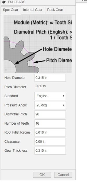
That looks like more than I want to get into. Here is what you have to fill in when using FM Gears. A module in Fusion 360. FM Gears.jpg
 
Top